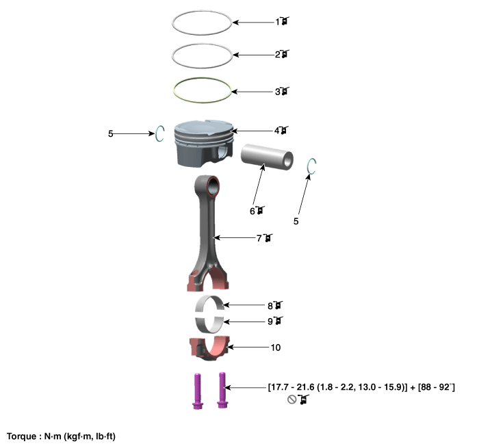
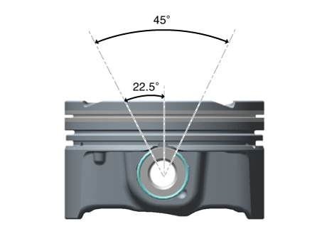
| 2. |
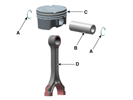
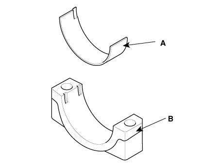
Check the connecting rod bearing oil clearance.
| (1) |
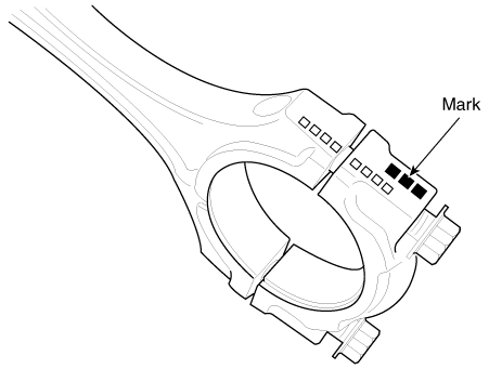
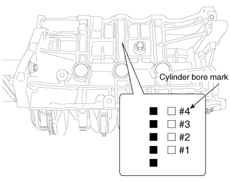
Check the match marks on the connecting rod and cap are aligned
to ensure correct reassembly.
|
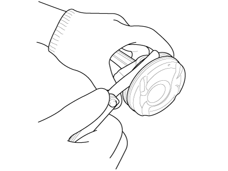
| (2) |
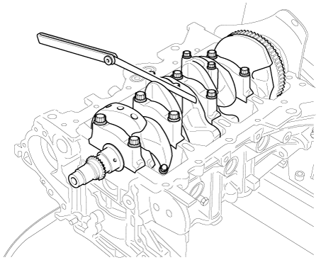
Remove the 2 connecting rod cap bolts.
|
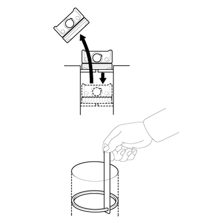
| (3) |
Remove the connecting rod cap and lower bearing.
|
| (4) |
Clean the crankshaft pin journal and bearing.
|
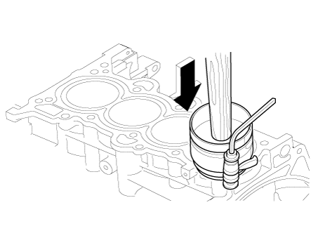
| (5) |
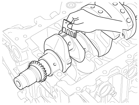
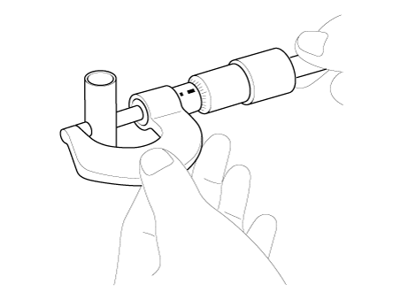
Place a plastigage across the crankshaft pin journal.
|
| (6) |
Reinstall the lower bearing and cap, and tighten the bolts.
|
Tightening torque :
17.7 - 21.6 N·m (1.8 - 2.2 kgf·m, 13.0 - 15.9 lb·ft)
+ 88° - 92°
|
|
• |
Do not turn the crankshaft.
|
|
• |
Always use new connecting rod cap bolts. Connecting
rod cap bolts are torque - to - yield bolts designed
to be permanently elongated beyond the state of
elasticity when torqued, so if the bolts are removed
and reused, it may cause the bolts to break or fail
to maintain clamping force.
|
|
|
| (7) |
Remove the connecting rod cap and lower bearing.
|
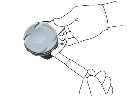
| (8) |
Measure the plastigage at its widest point.
|
Bearing oil clearance :
0.030 - 0.050 mm (0.0012 - 0.0020 in)
|
|
| (9) |
If the measurement from the plastigage is too wide or too narrow,
remove the upper and lower bearing and then install a new bearings
with the same color mark.
Recheck the oil clearance.
|
Do not file, shim on scrape the bearings or the caps
to adjust clearance.
|
|
| (10) |
If the plastigage shows the clearance is still incorrect, try
the next larger or smaller bearing. Recheck the oil clearance.
|
If the proper clearance cannot be obtained by using the
appropriate larger or smaller bearings, replace the crankshaft
and start over.
|
|
If the marks are indecipherable because of an accumulation
of dirt and dust, do not scrub them with a wire brush or
scraper. Clean them only with solvent or detergent.
|
|
| (11) |
Select the bearing by using the selection table.
Connecting Rod Bearing Selection
Table
Connecting rod bearing
|
Connecting rod mark
|
A, 0
|
B, 00
|
C, 000
|
Crank shaft pin journal mark
|
1
|
E (Pink)
|
D (Light Green)
|
C (White)
|
2
|
D (Light Green)
|
C (White)
|
B (Black)
|
3
|
C (White)
|
B (Black)
|
A (Light Blue)
|
Inspection Of Connecting Rod
Mark
|
Connecting rod big - end inner diameter
|
A, 0
|
45.000 - 45.006 mm
(1.7717 - 1.7719 in)
|
B, 00
|
45.006 - 45.012 mm
(1.7719 - 1.7721 in)
|
C, 000
|
45.012 - 45.018 mm
(1.7721 - 1.7724 in)
|
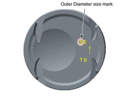
Inspection Of Crankshaft Pin Journal
Mark
|
Crankshaft pin journal outer diameter
|
1
|
41.966 - 41.972 mm
(1.6522 - 1.6524 in)
|
2
|
41.960
- 41.966 mm
(1.6520 - 1.6522 in)
|
3
|
41.954 - 41.960 mm
(1.6517 - 1.6520 in)
|
[Type A]
Top surface stamp
[Type B]
Bottom surface stamp
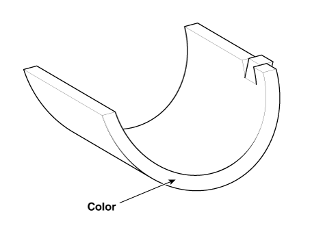
Inspection Of Connecting Rod Bearing
Class
|
Color
|
Connecting rod bearing thickness
|
A
|
Light
Blue
|
1.514 - 1.517 mm
(0.0596 - 0.0597 in)
|
B
|
Black
|
1.511 - 1.514 mm
(0.0595 - 0.0596 in)
|
C
|
White
|
1.508 - 1.511 mm
(0.0594 - 0.0595 in)
|
D
|
Light
Green
|
1.505 - 1.508 mm
(0.0593 - 0.0594 in)
|
E
|
Pink
|
1.502 - 1.505 mm
(0.0591 - 0.0593 in)
|
|
|


 Rear Oil Seal
 Crankshaft