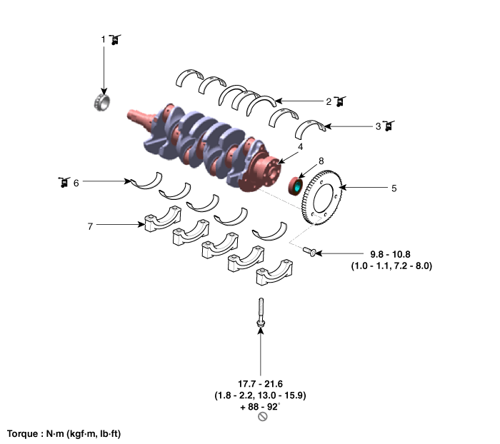
Kia Forte: Cylinder Block / Crankshaft

Kia Forte 2019-2024 (BD) Service Manual / Engine Mechanical System / Cylinder Block / Crankshaft

Components and components location
Components

1. Crankshaft sprocket
2. Crankshaft thrust bearing
3. Crankshaft upper main bearing
4. Crankshaft
5. CKPS wheel
6. Crankshaft lower main bearing
7. Crankshaft main bearing cap
8. Pilot bearing (Dual clutch transmisson (DCT) only)


Repair procedures
Disassembly
  

Use fender covers to avoid damaging painted surfaces.

To avoid damaging the cylinder head, wait until the engine coolant temperature drops below normal temperature (20°C [68°F]) before removing it.

When handling a metal gasket, take care not to fold the gasket or damage the contact surface of the gasket.

To avoid damage, unplug the wiring connectors carefully while holding the connector portion.


Mark all wiring and hoses to avoid misconnection.

Turn the crankshaft damper pulley so that the piston of No. 1 cylinder is at TDC (top dead center) on compression stroke.

1.

Remove the engine and transmission assembly from the vehicle.

(Refer to Engine and Transmission Assembly - "Engine and Transmission Assembly")

2.

Remove the transaxle assembly.

Manual Transaxle System:

(Refer to Manual Transaxle System - "Manual Transaxle")

DCT (Double Clutch Transmission) System :

(Refer to DCT (Double Clutch Transmission) System - "DCT (Double Clutch Transmission)")

3.

3. Remove the flywheel.

(Refer to Cylinder Block - "Flywheel")

4.

Remove the rear oil seal.

(Refer to Cylinder Block Assembly - "Rear Oil Seal")

5.

Install the engine assembly to engine stand for disassembly.

6.

Remove the intake manifold.

(Refer to Intake and Exhaust System - "Intake Manifold")

7.

Remove the exhaust manifold.

(Refer to Intake and Exhaust System - "Exhaust Manifold")

8.

Remove the timing chain.

(Refer to Timing System - "Timing Chain")

9.

Remove the cylinder head assembly.

(Refer to Cylinder Head Assembly - "Cylinder Head")

10.

Remove the oil cooler.

(Refer to Lubrication System - "Oil Cooler")

11.

Remove the oil pan and the oil screen.

(Refer to Lubrication System - "Oil Pan")

12.

Remove the ladder frame (A).

13.

Remove the piston and connecting rod assembly.

(Refer to Cylinder Block Assembly - "Piston and Connecting Rod")

14.

Check the crank shaft main bearing oil clearance.

15.

Remove the main bearing caps (A).

16.

Check the crankshaft end play.

17.

Remove the crankshaft (A) out of the cylinder block, being careful not to damage journals.


Arrange the main bearings and thrust bearings in the correct order.

Keep the main bearing caps with their bearings assembled together.

18.

Remove the CKPS wheel (A) from the crankshaft.

Inspection

Pilot bearing

1.

Inspect the pilot bearing.

(1)

Check if the pilot bearing (A) is damaged visually.

(2)

Check if there is noise by rotating the inner shell (A) of pilot bearing.

(3)

If a damage or noise is found, then relpace the crankshaft with the pilot bearing.


Be sure to replace the crankshaft and pilot bearing together, because crankshaft can be damaged or deformed when removing the pilot bearing.

Crankshaft

1.

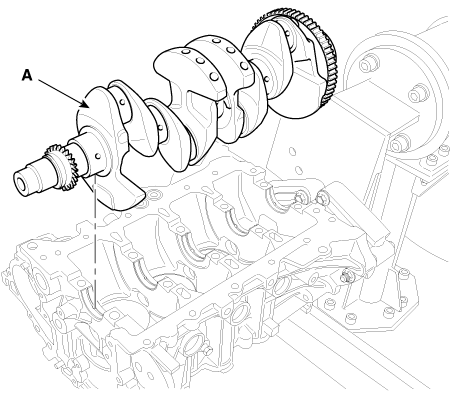
Check the crankshaft main bearing oil clearance.

(1)

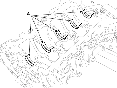
To check main bearing - to - journal oil clearance, remove the bearing caps with their lower bearings.

(2)

Clean each main journal and lower bearing with a clean shop towel.

(3)

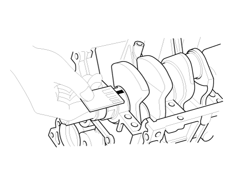
Place one strip of plastigage across each main journal.

(4)

Reinstall the bearing caps with their lower bearings, then tighten the bolts.

Tightening torque :

17.7 - 21.6 N·m (1.8 - 2.2 kgf·m, 13.0 - 15.9 lb·ft) + 88 - 92°


Always use new crankshaft main bearing cap bolts. Crankshaft main bearing cap bolts are toque - to - yield bolts designed to be permanently elongated beyond the state of elasticity when torqued, so if the bolts are removed and reused, it may cause the bolts to break or fail to maintain clamping force.

Do not turn the crankshaft.

(5)

Remove the bearing caps with their lower bearing again, and measure the widest part of the plastigage.

Oil clearance

No.1, 2, 3, 4, 5 : 0.020 - 0.041 mm (0.0008 - 0.0016 in)

(6)

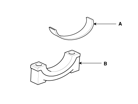
If the plastigage measures too wide or too narrow, remove the upper and lower bearing and then install a new bearings with the same color mark. Recheck the oil clearance.


Do not file, shim, or scrape the bearings or the caps to adjust clearance.

(7)

If the plastigage shows the clearance is still incorrect, try the next larger or smaller bearing. Recheck the oil clearance.


If the proper clearance cannot be obtained by using the appropriate larger or smaller bearings, replace the crankshaft and start over.


If the marks are indecipherable because of an accumulation of dirt and dust, do not scrub them with a wire brush or scraper. Clean them only with solvent or detergent.

(8)

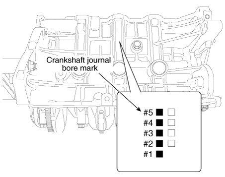
Select the bearing by using the selection table.

Letters have been stamped on the side of block as a mark for the size of each of the 5 main journal bores.

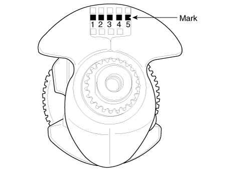
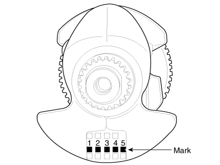
Use them, and the numbers or letters stamped on the crank (marks for main journal size), to choose the correct bearings.

Crankshaft Main Bearing Selection Table

Crankshaft main bearing
Cylinder block crankshaft journal bore mark
A
B
C
Crankshaft main journal mark
1
E (Red / Yellow)
D (Green)
C (None)
2
D (Green)
C (None)
B (Black)
3
C (None)
B (Black)
A (Blue)

Inspection Of Cylinder Block Crankshaft Journal Bore

Mark
Cylinder block journal bore inner diameter
A or 1
52.000 - 52.006 mm
(2.0472 - 2.0475 in)
B or 2
52.006 - 52.012 mm
(2.0475 - 2.0477 in)
C or 3
52.012 - 52.018 mm
(2.0477 - 2.0479 in)

Inspection Of Crankshaft Main Journal

Mark
Crankshaft main journal outer diameter
1
47.954 - 47.960 mm
(1.8879 - 1.8882 in)
2
47.948 - 47.954 mm
(1.8877 - 1.8879 in)
3
47.942 - 47.948 mm
(1.8875 - 1.8877 in)

[Type A]

Top surface stamp

[Type B]

Bottom surface stamp

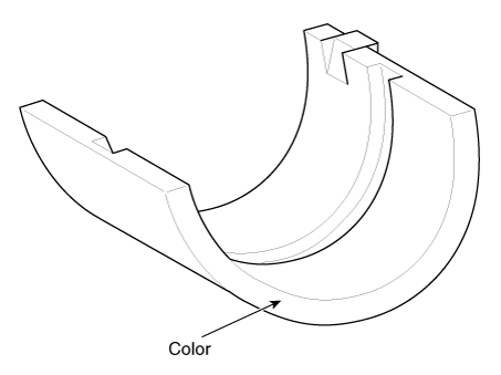
Inspection Of Crankshaft Main Bearing

Class
Color
Crankshaft main bearing thickness
A
Blue
2.026 - 2.029 mm
(0.0798 - 0.0799 in)
B
Black
2.023 - 2.026 mm
(0.0796 - 0.0798 in)
C
None
2.020 - 2.023 mm
(0.0795 - 0.0796 in)
D
Green
2.017 - 2.020 mm
(0.0794 - 0.0795 in)
E
Red / Yellow
2.014 - 2.017 mm
(0.0793 - 0.0794 in)

2.

Check the crankshaft end play.

Using a dial indicator, measure the thrust clearance while prying the crankshaft back and forth with a screwdriver.

Crankshaft end play

Standard : 0.05 - 0.25 mm (0.0020 - 0.0098 in)

Limit : 0.30 mm (0.0118 in)

If the end play is greater than specification, replace the center bearing.

Reassembly
  

Thoroughly clean all parts to assembled.

Before installing the parts, apply fresh engine oil to all sliding and rotating surfaces.

Replace all gaskets, O - rings and oil seals with new parts.

1.

Check if the pilot bearing (A) is installed in the crankshaft when replacing the crankshaft or short engine.

If being not installed, be sure to install the pilot bearing (A).


Be sure to replace the crankshaft and pilot bearing together, because crankshaft can be damaged or deformed when removing the pilot bearing.

Be sure to force on only outer shell of pilot bearing because when forcing on the pilot bearing seal or inner shell, it can be damaged.

Install the pilot bearing to the crank shaft as the illustration below.

Press force :

180 - 920 N (18 - 94 kgf , 40 - 206 lbf)

Press depth :

1.5 - 2.0 mm (0.0591 - 0.0787 in.)

2.

Install the CKPS wheel (A).

Tightening torque :

9.8 - 10.7 N·m (1.0 - 1.1 kgf·m, 7.23 - 7.95 lb·ft)

3.

Install the crankshaft main bearings.


Upper bearings have an oil groove of oil holes ; Lower bearings do not.

(1)

Align the bearing claw with the claw groove of the cylinder block, and push in the 5 upper bearings (A).

(2)

Align the bearing claw with the claw groove of the main bearing cap (B), and push in the 5 lower bearings (A).

(3)

Apply a coat of engine oil after assembling the main bearings.

4.

Install the thrust bearings (No.3 journal).

Install the 2 thrust bearings (B) on both sides of the No.3 journal of the cylinder block with the oil groove (A) facing out.

5.

Place the crankshaft on the cylinder block.

Apply a coat of engine oil to the pin and main journals after assembling the crankshaft.

6.

Install the main bearing caps and tighten the cap bolts.


Always use new crankshaft main bearing cap bolts. Crankshaft main bearing cap bolts are torque - to - yield bolts designed to be permanently elongated beyond the state of elasticity when torqued, so if the bolts are removed and reused, it may cause the bolts to break or fail to maintain clamping force.

Be sure to assemble the main bearing caps in correct order.

Install the main bearing cap with the arrow facing the front of the engine.

Tighten all the main bearing cap bolts with the specified torque first, and then retighten all the bolts with the specified angle.

(1)

Apply a light coat of engine oil on the threads of the bolts. Tighten all the bolts with the specified torque in numerical order first, then tighten all the bolts with the specified angle in numerical order.

Tightening torque :

17.7 - 21.6 N·m (1.8 - 2.2 kgf·m, 13.0 - 15.9 lb·ft) + 88° - 92°

Using the SST (09221 - 4A000), tighten the main bearing cap bolts (A).

(2)

Check that the crankshaft turns smoothly.

7.

Check the crankshaft end play.

8.

Install the piston and connecting rod assemblies.

(Refer to Cylinder Block Assembly - "Piston and Connecting Rod")

9.

Install the ladder frame.

(1)

Apply the liquid gasket on the ladder frame.

Bead width : 2.5 - 3.5 mm (0.0984 - 0.1378 in)


Apply the sealant, THREE-BOND 1217H or LOCTITE 5900H on the ladder frame rail portion and install it within five minutes. If sealant is applied to cylinder block bottom position, the sealant position should be the same as that of the ladder frame rail.

Apply sealant along the inner line of the bolt holes.

(2)

Install the ladder frame (A).

Tightening torque :

18.6 - 23.5 N·m (1.9 - 2.4 kgf·m, 13.7 - 17.4 lb·ft)

10.

Install the other parts in the reverse order of disassembly.


In case the crankshaft is replaced with a new one, select the proper connecting rod bearing according to the pin journal mark on the crankshaft.

Connecting rod bearing selection

(Refer to Cylinder Block Assembly - "Piston and Connecting Rod")

Piston and Connecting Rod
Components and components location Components 1. Piston ring (#1) 2. Piston ring (#2) 3. Oil ring 4. Piston 5. Snap ring 6. Piston pin 7. Connect ...

Cylinder Block
Repair procedures Disassembly    • Use fender covers to avoid damaging painted surfaces. ...

Other information:

Kia Forte 2019-2024 (BD) Owners Manual: On inclines, Lane changing


On inclines During uphill or downhill driving, the smart cruise control system may not immediately detect a moving vehicle in your lane, and may cause your vehicle to accelerate to the set speed. Also, the vehicle speed may rapidly decrease when the vehicle ahead is sudden ...

Kia Forte 2019-2024 (BD) Owners Manual: Smart Cruise Control


➀ Cruise indicator ➁ Set speed ➂ Vehicle-to-vehicle distance The smart cruise control system allows you to program the vehicle to maintain a constant speed and predetermined distance to the vehicle ahead without depressing the accelerator or brake pedal. WARNING For your saf ...

Copyright © www.kiforte.com 2017-2024