Kia Forte: Button Engine Start System / ESCL(Electronic Steering Column Lock)
Kia Forte 2019-2025 (BD) Service Manual / Body Electrical System / Button Engine Start System / ESCL(Electronic Steering Column Lock)
Schematic diagrams
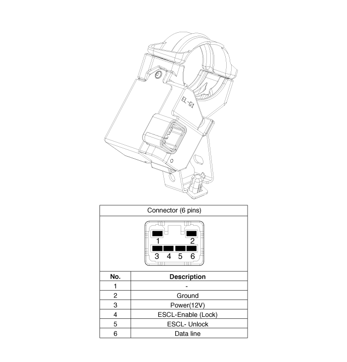
| Connector and Terminal funciton |

Repair procedures
| Removal |
| 1. |
Disconnect the negative(-) battery terminal. |
| 2. |
Remove the crash pad lower panel. (Refer to Body - "Crash Pad Lower Panel") |
| 3. |
Remove the steering column upper and lower shrouds. (Refer to Body - "Steering Column Shroud Panel") |
| 4. |
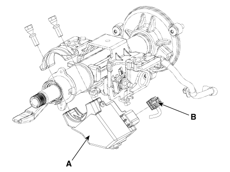
Remove the electronic steering column lock (A) by loosening the mounting bolts after disconnecting the connector (B).
|
| Installation |
| 1. |
Install in the reverse order of removal.
|
 Start/Stop Button
Schematic diagrams
Connector and Terminal function
Repair procedures
Removal
1.
Disconnect the negative (-) battery terminal.
2.
R ...
 Charging System
Components and components location
Components
1. Wireless power charger (WPC)
2. Wireless Charging indicator
3. Front USB charger
4. Rear USB charger
...
Other information:
Kia Forte 2019-2025 (BD) Service Manual: Room Lamp
Repair procedures Removal When removing with a flat-tip screwdriver or remover, wrap protective tape around the tools to prevent damage to components. 1. Disconnect the negative (-) batt ...
Kia Forte 2019-2025 (BD) Service Manual: External AMP
Components and components location Components Location 1. Amplifier assembly Schematic diagrams Connector and Terminal function [KRELL] No. Connector A Connector B 1 ...
Copyright © www.kiforte.com 2017-2025


