Kia Forte: Charging System / Wireless Charging Indicator
Specifications
Items
|
Specification
|
Operating voltage
|
9 - 16.0 V
|
Operating temperature
|
-30 - +75°C
|
Control method
|
PWM control
|
LED Output
|
Charging in process : Amber LED turned ON
|
Charging completed : Green LED turned ON
|
Schematic diagrams
| Connector and Terminal function |
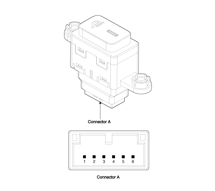
No.
|
Description
|
1
|
Ground
|
2
|
LED charging lamp (Green)
|
3
|
LED charging lamp (Amber)
|
4
|
-
|
5
|
Illumination (-)
|
6
|
Illumination (+)
|
Repair procedures
| • |
When prying with a flat-tip screwdriver or use a prying trim
tool, wrap it with protective tape, and apply protective tape around
the related parts, to prevent damage.
|
| • |
a plastic panel removal tool to remove interior trim pieces to
protect from marring the surface.
|
| • |
Take care not to bend or scratch the trim and panels.
|
|
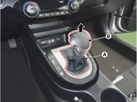
| 1. |
Disconnect the negative (-) battery terminal.
|
| 2. |
Remove the knob (B) by pulling them in the direction of the arrow after
separating the boots (A) from the console upper cover.
|
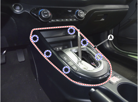
| 3. |
Remove the console upper cover (A).
|
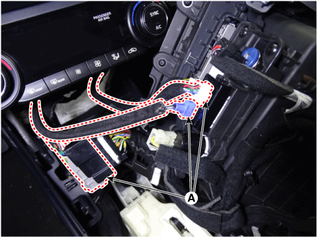
| 4. |
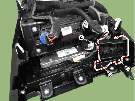
Disconnect the connector (A) from the console upper cover.
|
| 5. |
Remove the connector (A) after loosening the screws.
|
| 6. |
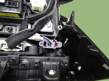
Remove the wireless charging indicator (A) by loosening the screws after
disconnecting the connector.
|
| 1. |
Install in the reverse order of removal.
|
Specifications
Specifications
Items
Specification
Rated voltage
DC 13.5 V
Operating voltage
DC 8.5 - ...
Specifications
Specifications
Items
Specification
Operating voltage
9 - 16.0 V
Operating temperature
...
Other information:
Repair procedures
Replacement
Put on gloves to prevent hand injuries.
•
When removing with a flat - tip screwd ...
Components and components location
Components Location
1. Control shaft complete
Repair procedures
Removal
1.
Shift the gear to "neutral".
2.
Remove the air cleaner assembly and air duct.
(Refer to Engine Mechanical ...

 Wireless Power Charger (WPC)
 USB Charger