Kia Forte: Fuses And Relays / Integrated Central Control Unit (ICU)
Components and components location
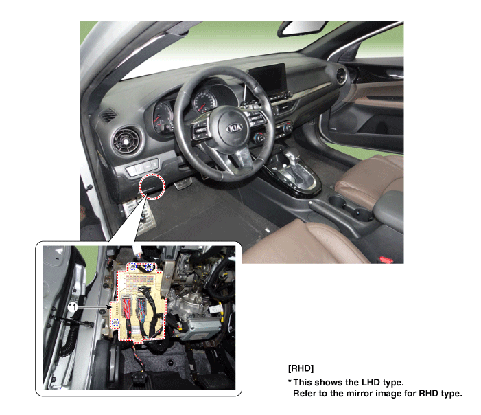
1. Integrated central control
unit (ICU)
|
|
Description and operation
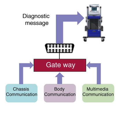
Communication Network Diagram
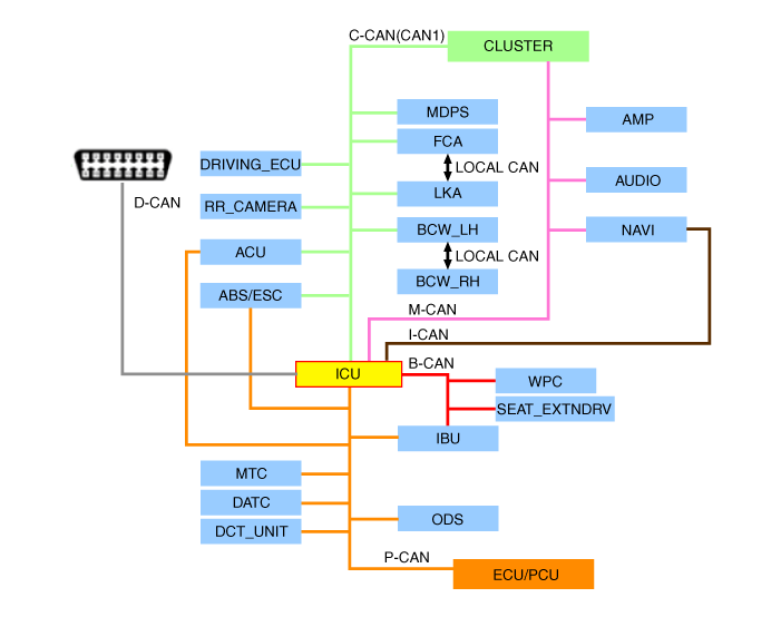
Abbreviation
|
Explanation
|
ACU
|
Airbag Control Unit
|
MDPS
|
Motor Driven Power Steering
|
LKA
|
Lane Keeping Assist
|
BCW
|
Blind-Spot Collision Warning
|
IBU
|
Integrated Body Control Unit
|
ICU
|
Integrated Central Control Unit
|
MTC
|
Manual Temp Control
|
DATC
|
Dual Automatic Temp Control
|
ODS
|
Occupant Detection System
|
PCU
|
Powertrain control module
|
ABS
|
Anti-Lock Braking System
|
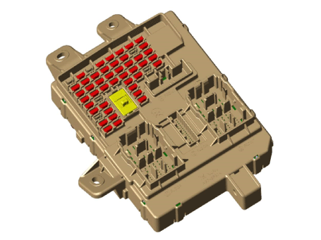
Integrated Central Control Unit (ICU)
ICU (Integrated Central Control Unit) is an integrated model of smart junction
block and central gateway.
It performs the function of conventional "Smart junction block" and the function
of communication medium of "Central Gateway".
Central Gateway (CGW)
CGW is a controller enabling communication among the controllers connected to
the different networks.
There are five CAN networks connected to CGW. B-CAN and M-CAN are connected to
the low-speed CAN, C-CAN and P-CAN to the high-speed CAN while D-CAN is connected
for inspection.
| 1. |
CGW Main Features
| (1) |
Routing : Information exchange among different in-vehicle communication
networks.
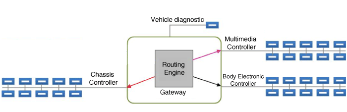
|
| (2) |
Network security control : It only allows inspection communication
(D-CAN) to connect in-vehicle communication network in order to
prevent
|
| (3) |
Additional functions
| •
|
If alarm light is ON, carry out remote diagnosis of Chassis
system (C-CAN) through I-Box and gateway
|
I-Box remote diagnosis (C-CAN) function via gateway
shall be suspended.
|
|
| •
|
Dark current measurement: After sending forced electronic
parts sleep message to each network from the diagnosis equipment,
gateway also enters sleep mode.
|
| •
|
Operation current check: Check problem through operation
of electronic parts
|
|
| (4) |
Fault diagnosis on CAN signal transmission failure by communication
control defect
(CGW records DTC for the controller with transmission failure.)
|
|
| 2. |
How to check CGW
| (1) |
Although "No CGW CAN signal (TIMEOUT)" record appears when checking
the DTC of the faulty electronic component, never determine it as
the CGW failure. CGW is a controller that intermediates in-vehicle
transmitting/receiving controllers. If one of the following two
cases arises : (1) the transmitting controller fails to send a message
to CGW, leading to CGW failing to send it to the receiving controller;
(2) CGW sends the pre-determined value (Timeout Value), the corresponding
receiver records the DTC of the failure of message transmission.
Thus, to finally determine the controller that fails to send CAN
signal, the DTC of CGW shall be checked. CGW records DTC only when
it fails to receive the signal for more than 10 seconds with KEY
ON. To identify the cause of no CAN signal transmission, the CGW
DTC shall be checked after waiting for more than 20 seconds with
KEY ON.
|
| (2) |
If the CAN communication control unit is not reinstalled after
being removed from the vehicle, CGW records the DTC of 'No CAN signal'
for the unit.
|
For example, the failure code of 'DDM CAN signal is not
out' is created when the removed DDM is not reinstalled.
|
If a DTC remains after replacing electronic components and the
failure code is not erased, check whether the connector of the electronic
component is properly connected, and whether the controller's CAN
wiring operates normally. In case that the removed electronic component
cannot be reinstalled, ‘Erase Expected Network Config' service shall
be performed. Refer to the DTC inspection guide for each failure
code for the service execution method.
Otherwise, the DTC of "No CAN Signal" on the corresponding controller
may not be deleted.
|
Perform the "Additional function" > "Network setting
initialization" in examining device (KDS) by referring to
DTC guide.
|
|
| (3) |
IGN2 of SJB is ON when MCU is out of order (State of non-operation
due to the external physical or electrical shock). The safety of
the driver is secured by forcible lighting on the head lamp low,
external and internal tail lamps when the headlamp low switch is
ON.
|
| (4) |
IGN2 is ON when the data transmitting/receiving is impossible
by the failure on the CAN communication line (Both of high/low cables
are shorted, BAT short in high/low, GND short in high/low) in case
of failure on CAN communication line connected to SJB module. When
the headlamp low switch is ON, the headlamp low and internal/external
tail lamps are lighted forcibly.
|
|
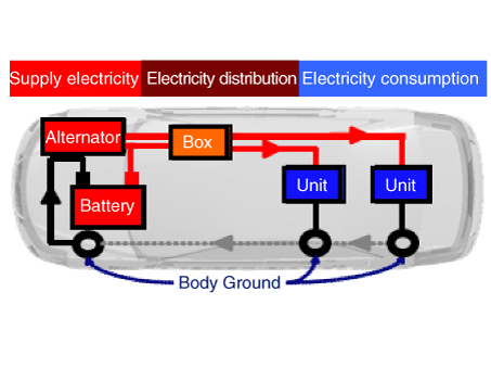
Smart Junction Block(SJB)
Smart Junction Block (SJB) is a module that performs the function of conventional
Junction Box and some functions of IBU.
It controls various components including lamps by using CAN communication and
IPS (replacing the function of fuse and relay) or ARISU.
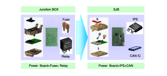
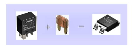
IPS stands for Intelligent Power Switch, which uses the semiconductor technology
to replace the current role of fuse and relay.
The IPS chip has two functions :
1) the high current-based component control;
2) component protection from overcurrent.
|
The advantages of IPS are as follows:
| – |
Reduce relay and consequently decrease weight and volume
|
| – |
Remove the relay operation noise
|
| – |
No need to replace fuses and increase the product life
|
| – |
Capable to diagnose faulty parts
|
|
SJB control entry
| 1. |
Switch signal input
| (1) |
Assist seat belt switch
Assist seat belt reminder switch
Assist the door switch
Driver's seat belt switch
Driver's seat belt switch
Rear left seats door switch
Rear right seats door switch
Rear Safety seat belt switch Left
Rear Safety seat belt switch Right
Rear Center seat safety belt switch
IGN1 switch
IGN2 switch
Brake fluid sensor
Trunk open switch
Trunk lid handle switch
HID head lamp option
ADV HID head lamp option
Emergency switch
Headlight low beams switch
Hood switch
Dark disconnect switch
Left front / rear turn signal switch
Right front / rear turn signal switch
|
| (2) |
IPS&ARISU
Left Headlight low beams
Right Headlight low beams
Right Headlight high beams
Right Headlight high beams
Front left / right fog lamp
Room Taillight
Outdoor Left taillight
Outdoor Light taillight
Left front / rear turn signals
Right front / rear turn signals
Static bending left lamps
Static bending right lamp
DRL Left lamp
DRL right lamp
Trunk room lamp
Body resistance Cut control
Front left turn signal output
Front right turn signal output
|
| (3) |
Relay Control
Rear glass heat rays relay
Anti-theft alarm horn relay
Trunk lid relay
Room lamp relay
Front glass heat rays relay
Rear fog lamp relay
Headlight high beams relay
|
|
| 2. |
SJB protection
| (1) |
PCL (Programmable Current Limit) functions
| –
|
PCL replaces the junction box function of protecting
wires.
|
| –
|
How to operate : If the lamp current exceeds the standard
level, cut off the current to protect the lamp.
|
| –
|
Lamp cut off time : 300ms or less.
|
| –
|
Applied components : all lamp components controlled by
SJB
|
| –
|
Output the error code according to the error detection
conditions.
|
|
| (2) |
OCL (Open Current Limit)
| –
|
OCL detects the lamp open state and informs the user
of it.
|
| –
|
How to operate : Detect the current of the lamp and if
it is below the standard level, change the lamp operation.
|
| –
|
Applied components : 4 turn signal lamps
|
| –
|
Output the error code according to the error detection
conditions.
|
|
|
| 3. |
SJB fail safe function
| (1) |
When the MCU is out of order (not operating due to a physical
or electrical shock from the outside), and IGN2 and head lamp low
switch are on, SJB forces the head lamp low and exterior/interior
lamps to turn on in order to secure the driver’s safety.
|
| (2) |
When the data transmission/reception fails due to a failed CAN
communication line connected with SJB module (disconnection of both
high and low line, high/low BAT short, high/low GND short), the
head lamp low and interior/exterior tail lamps are forced to turn
on if IGN2 is on and the head lamp low switch is on.
|
|
| 4. |
Auto Cut System of Dark Current
| (1) |
Description : It cuts automatically power to be provided with
components for reducing useless dark current according to vehicle
state.
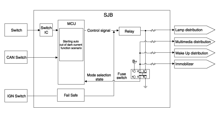
|
| (2) |
SJB had 3 modes, "Normal Mode", "Sleep Mode", "Power Off Mode".
Auto cut of dark current practice in "Sleep Mode".
| –
|
"Sleep" condition : IG OFF, constant input switch, CAN
network doesn't activate.
|
| –
|
"Sleep" resolutive condition : Any switch inputs, CAN
network activates, KEY ON, IGN ON
|
| –
|
"Power OFF" condition : The setting time of timer which
is used by cutting a load power expires.
|
| –
|
"Normal Mode" : SJB function normally activates.
|
| –
|
"Sleep Mode" : It is low power mode and activates for
reducing electricity consumption of SJB or IPM. Auto cut
of dark current function activates.
|
| –
|
"Power OFF Mode" : Power of MCU and circumferential circuit
is cut for minimizing electricity consumption. Operation
stops.
|
|
| (3) |
The explanation - The auto cut of dark current
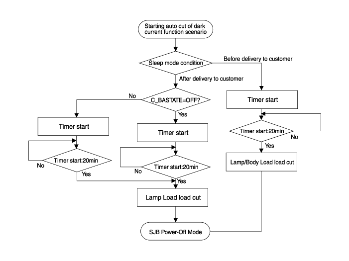
Before delivering to customer
|
Fuse switch OFF
|
|
• |
All door close & RKE door lock or Constant switch
state
(Auto cut of dark current scenario starts.)
|
|
– |
After "sleep" state is for 20 min.
|
|
– |
SJB power down(SJB dark current : 200 μA) and
cutting power of Lamp
/Body Load/Wake up
|
|
|
After delivering to customer
|
Fuse switch ON
|
|
• |
All door close & Constant switch state : C_BAState=OFF
(Auto cut of dark current scenario starts.)
|
|
– |
After "sleep" state is for 20 min.
|
|
– |
SJB power down(SJB dark current : 200 μA) and
cutting power of Lamp Load
|
|
• |
In case RKE door lock : C_BAState=ON & Trunk
SW=CLOSE
(Auto cut of dark current scenario starts.)
|
|
– |
After "Sleep" state 35s-65s (Waiting time of
other unit : 30-60s + SJB
sleep counts 5s)
|
|
– |
SJB Powerdown(SJB dark current : 200 μA) and
cutting power of
Lamp Load
|
|
|
|
| (4) |
Problem when fuse switch setting is wrong
: If a fuse switch is set to OFF(Before delivering to customer)
by a customer or technician and auto cut function of dark current
activates, the following problems may occur.
Symptom
|
Related part
|
|
• |
Door lock/unlock, trunk open don't activate by
RKE.
(Wakeup of each module don't activate.)
|
|
IBU
|
|
• |
Digital clock is reset.(Memory is reset.)
|
|
Digital clock
|
|
• |
Audio setting values (volume, frequency setting)
are reset.
(Memory is reset.)
|
|
Audio
|
* If fuse switch OFF(before delivering to customer) is set, power
of IBU, Digital clock and audio is shut off.
|
|
Repair procedures
| 1. |
Check that the fuse holders are loosely held and that the fuses are securely
fixed by the holders.
|
| 2. |
Check that each fuse circuit has the exact fuse capacity.
|
| 3. |
Check the fuses for any damage.
|
If a fuse is to be replaced, be sure to use a new fuse of the
same capacity. Always identify the cause of the blown fuse and completely
eliminate the problem before installing a new fuse.
|
|
| 1. |
In the body electrical system, failure can be quickly diagnosed by using
the vehicle diagnostic system (KDS).
The diagnostic system (KDS) provides the following information.
| (1) |
Self diagnosis : Checking failure and code number (DTC).
|
| (2) |
Current data : Checking the system input/output data state.
|
| (3) |
Actuation test : Checking the system operation condition.
|
| (4) |
Additional function : Controlling other features including system
option setting and zero point adjustment.
|
|
| 2. |
Select the 'Car model' and the 'Integrated Central Control Unit (ICU)'
to be checked in order to check the vehicle with the tester.
|
| 3. |
Select the 'Current Data' menu to search the current state of the input/output
data.
|
| 4. |
To forcibly actuate the input value of the module to be checked, select
option 'Actuation Test'
|
| 5. |
If you want to change user option, select "user option".
|
| 1. |
Disconnect the negative (-) battery terminal.
|
| 2. |
Remove the crash pad lower panel.
(Refer to Body - "Crash Pad Lower Panel")
|
| 3. |
Remove the crash pad side switch assembly (A) after loosening the mounting
screws.
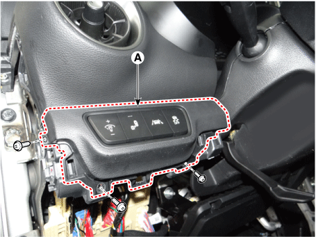
|
| 4. |
Disconnect the crash pad side switch assembly connector (A).
|
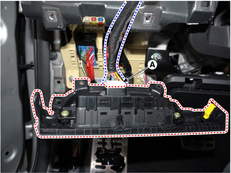
| 5. |
Remove the ICU (A) by loosening the nuts after disconnecting the connector.
|
| 6. |
Disconnect the connector (A) from the ICU.
|
| 1. |
Install in the reverse order of removal.
|
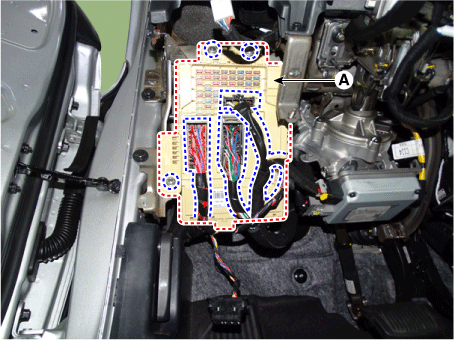
Components and components location
Components Location
[4DR]
1. Engine room junction block
[5DR]
1. Engine roo ...
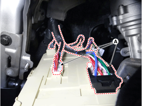
Schematic diagrams
Circuit Diagram
Repair procedures
Removal
1.
Disconnect the negative (-) battery terminal.
2.
Remove the crash ...
Other information:
1. Model Name
2. Maximum allowable load
3. When using the jack, set your
parking brake.
4. When using the jack, stop the
engine.
5. Do not get under a vehicle that is
supported by a jack.
6. The designated locations under
the frame
7. When supporting the vehicle, the
base pla ...
Schematic diagrams
Circuit Diagram
Repair procedures
Removal
1.
Disconnect the negative (-) battery terminal.
2.
Remove the crash pad lower panel.
(Refer to Body - "Crash Pad Lower Panel")
3.
...


 Engine Room Junction Block
 Headlamp Leveling Switch (Manual)