Kia Forte: Cylinder Head Assembly / Cylinder Head Cover
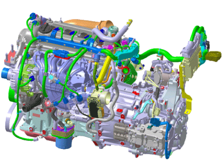
Components and components location
| Components |
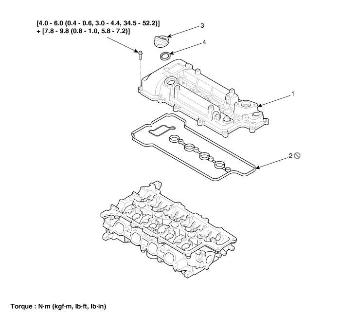
| 1. Cylinder head cover 2. Cylinder head cover gasket |
3. Oil cap 4. Cup packing |
Repair procedures
| Removal |
| 1. |
Remove the engine cover. (Refer to Engine and Transmission Assembly - "Engine Cover") |
| 2. |
Disconnect the battery negative terminal. |
| 3. |
Remove the air cleaner. (Refer to Intake and Exhaust System - "Air Cleaner") |
| 4. |
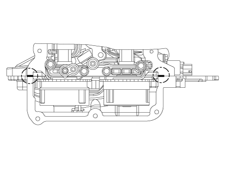
Disconnect the engine wiring connector and harness clamp and then remove the cylinder head protector and wiring from the cylinder head cover.
|
| 5. |
Remove the exhaust oil control valve (OCV). (Refer to Engine Control / Fuel System - "CVVT Oil Control Valve") |
| 6. |
Remove the ignition coil. (Refer to Engine Electrical System - "Ignition Coil") |
| 7. |
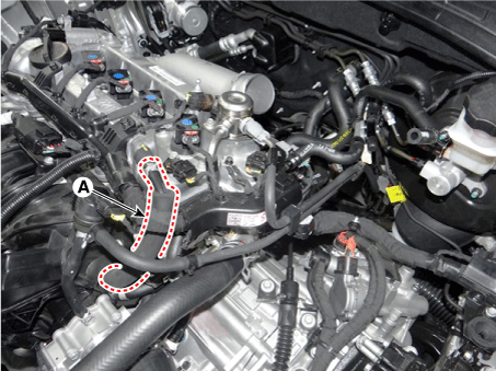
Disconnect the positive crankcase ventilation (PCV) hose (A).
|
| 8. |
Remove the high pressure fuel pump. (Refer to Engine Control / Fuel System - "High Pressure Fuel Pump") |
| 9. |
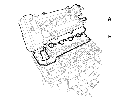
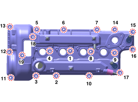
Remove the cylinder head cover (A), gasket (B).
|
| Installation |
| 1. |
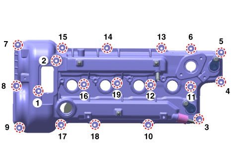
Install the cylinder head cover.
|
| 2. |
Install in the reverse order of removal. |
 Cylinder Head Assembly
Components and components location
Components
1. Cylinder head cover
2. Cylinder head cover gasket
3. Cylinder head assembly
4. Cylinder head gasket
5. Camsh ...
 CVVT & Camshaft
Components and components location
Components
1. Exhaust camshaft
2. Intake camshaft
3. Exhaust CVVT
4. Intake CVVT
5. Camshaft bearing cap
6. Camsha ...
Other information:
Kia Forte 2019-2025 (BD) Service Manual: A/C Pressure Transducer
Description and operation Description The A/C Pressure Transducer (APT) converts the pressure value of high pressure line into voltage value after measuring it. By converted voltage value, engine ECU controls the cooling fan by operating it high speed or low speed. Engine ECU stops ...
Kia Forte 2019-2025 (BD) Owners Manual: Mode selection
The mode selection knob controls the direction of the air flow through the ventilation system. Air can be directed to the floor, dashboard outlets, or windshield. Five symbols are used to represent Face, Bi-Level, Floor, Floor-Defrost and Defrost air position. Face-Level (B, D, F) ...

