Kia Forte: Dual Clutch Transmission Control System / Clutch Actuator Assembly
Components and components location
| Component Location |
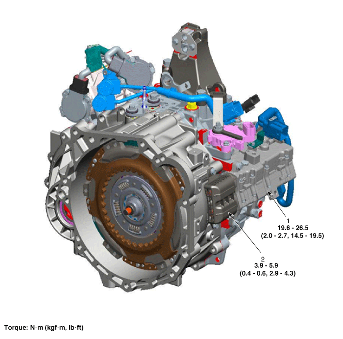
| 1. Clutch actuator assembly
|
2. Fork cover |
Specifications
| Specification |
|
Item |
Condition |
Specification |
|
Resistance (line to line) |
Motor 1 |
60 mΩ ±10 % |
|
Motor 2 |
64 mΩ ± 10 % |
|
|
Rated voltage |
12 V |
|
|
Operating condition |
-40 to 257°F (- 40 to 125°C) |
|
Description and operation
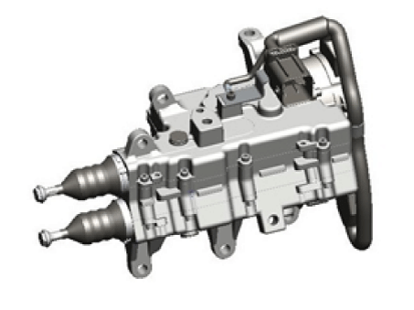
| Description |
The clutch actuator uses signals from the Transmission Control Module (TCM) to control the clutch.
Schematic diagrams
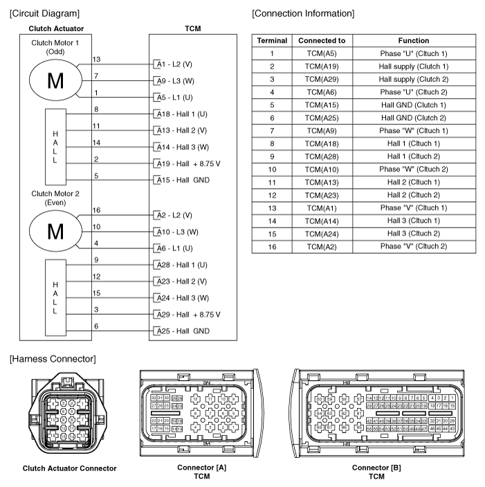
| Circuit Diagram |
| Video Clip |
Dual Clutch actuator Rod Adjust
(Dual Clutch Actuator Change)05:27

| Removal |
| 1. |
Remove the air cleaner assembly and air duct. (Refer to Engine Mechanical System - "Air cleaner") |
| 2. |
Remove the battery and battery tray. (Refer to Engine Electrical System - "Battery") |
| 3. |
Remove the inhibitor switch. (Refer to Dual Clutch Transmission Control System - "Inhibitor Switch") |
| 4. |
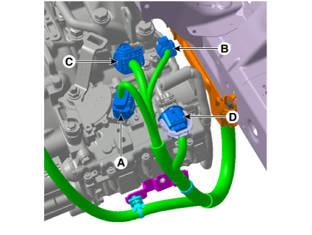
Disconnect the connectors (A, B ,C ,D) in the illustration below.
|
| 5. |
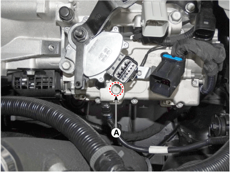
Loosen the ground bolt (A).
|
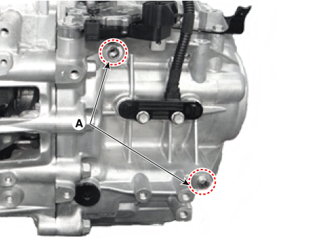
| 6. |
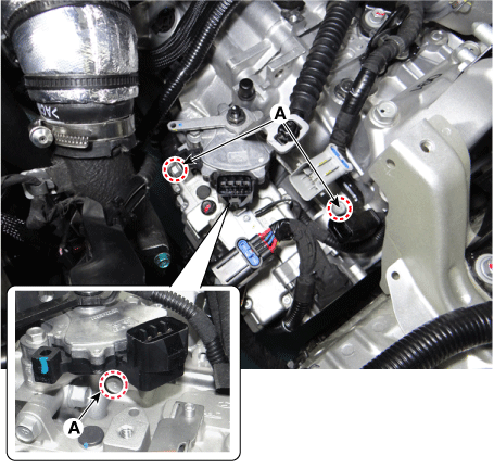
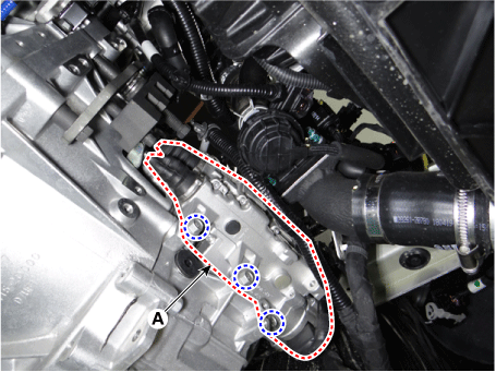
Loosen the clutch actuator mounting bolts (A).
|
| 7. |
Remove the under cover. (Refer to Engine Mechanical System - "Engine Room Under Cover") |
| 8. |
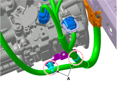
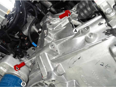
Remove the wiring bracket mounting clips (A).
|
| 9. |
Remove the vacuum pump. (Refer to Brake System - "Vacuum Pump") |
| 10. |
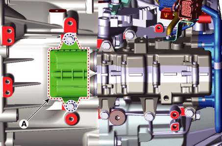
Remove the fork cover (A).
|
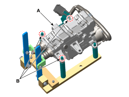
| 11. |
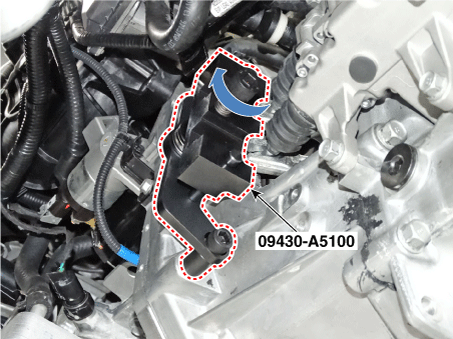
Install the special service tool (09430-A5100).
|
| 12. |
Remove the clutch actuator assembly (A) after loosening the bolts.
|
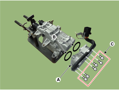
| 13. |
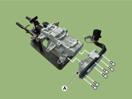
Remove the clutch actuator motor (A) if it is needed.
|
| Installation |
| 1. |
Install in the reverse order of removal.
|
| Adjustment |
(Refer to the video clip)
Make sure to proceed compensate wear procedure referring to table below incase of a dual clutch aseembly or a clutch actuator replacement.
|
| A. Rewinding rod length (if replacing a clutch actuator only) |
Make sure to perform rewinding rod length procedure if replacing a clutch actuator only and reusing a dual clutch assembly. This procedure is to adjust length of a new clutch actuator rod as an old clutch actuator rod length. |
| 1. |
Remove the clutch actuator. (Refer to Clutch Actuator Assembly - "Removal")
|
| 2. |
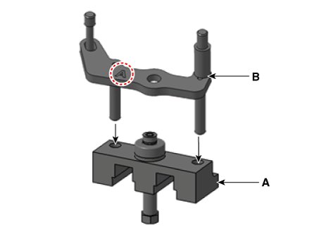
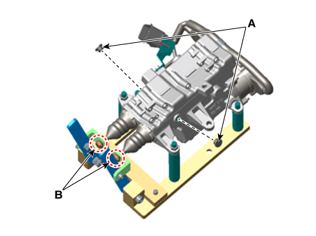
Fix the clutch actuator (A) which had been removed from vehicle with nut (B) after installing on SST (09430-C1302).
|
| 3. |
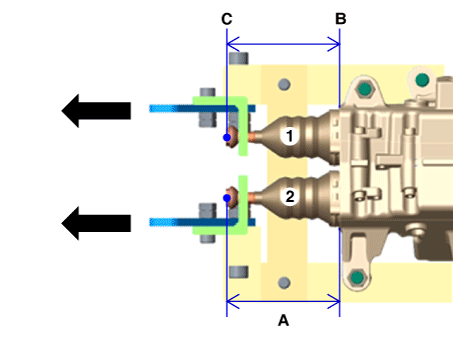
Measure and write down length of the old rod in condition of pulling clutch actuator lever.
|
| 4. |
Remove the clutch actuator from SST (09430-C1302).
|
| 5. |
Fix with nut (B) after installing the new clutch actuator (A) on SST (09430-C1302).
|
| 6. |
Fix the rod on hook (B) after removing sealing rubber (A).
|
| 7. |
Write down after measureing each length of the new rod (A) in condition of pulling the new clutch actuator lever.
|
| 8. |
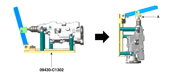
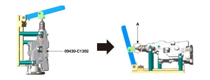
Stand clutch actuator vertically which is installed with SST (09430-C1302). |
| 9. |
Disassemble the clutch actuator hook (A) from the lever of SST.
|
| 10. |
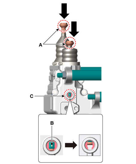
Press the end part of rod (A) and release the pressing force when you see the nut bump (B).
|
| 11. |
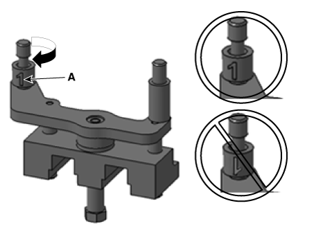
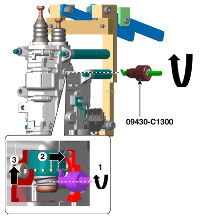
Put SST (09430-C1300) into sealing rubber hole. Adjust length of a new clutch actuator rod by rotating SST counterclockwise to 'an old rod length' which measured in procedure number 3.
|
| 12. |
Lay the clutch actuator horizontally with SST (09320-C1302) installed. |
| 13. |
Put the clutch actuator hook (A) into the SST lever.
|
| 14. |
Check if 'rod length of the clutch actuator', which is done with adjusting in state of pulling its lever, and 'rod length of the old clutch actuator', which is measured in step number 3, are same.
|
| 15. |
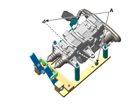
Install sealing rubber (A).
|
| 16. |
Remove the clutch actuator from SST (09430-C1302) |
| B. Rod length initialization (when replace only dual clutch assembly) |
Make sure to perform this procedure if replacing only dual clutch assembly but reusing clutch actuator. This procedure is adjusting changed existing clutch actuator rod length to a new product rod length. |
| 1. |
Remove the clutch actuator. (Refer to Clutch Actuator Assembly - "Removal") |
| 2. |
Fix the clutch actuator (A) which had been removed from vehicle with nut (B) after installing on SST (09430-C1302).
|
| 3. |
Fix the rod to hook after removing sealing cover (A).
|
| 4. |
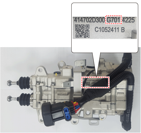
Initialization procedure will be needed if the measure value of each rod length, which measured in state of pulling lever on removed clutch actuator from vehicle, is shorter than initializing length specification.
|
| 5. |
Stand the clutch actuator vertically with SST (09430-C1302) installed. |
| 6. |
Remove the clutch actuator hook (A) from SST lever.
|
| 7. |
Press the end part of rod (A) and release the pressing force when you see the nut bump (B).
|
| 8. |
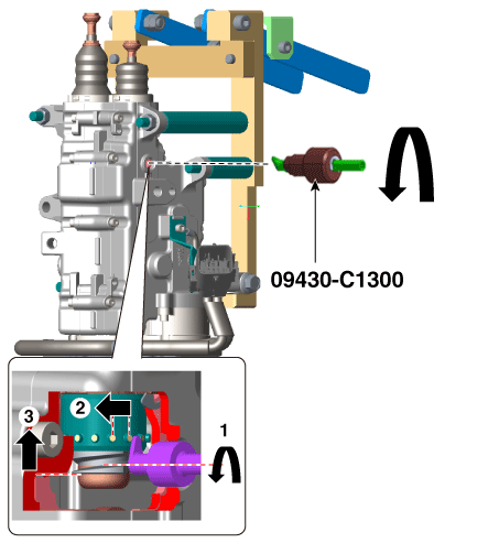
Put SST (09302-C1300) into sealing rubber hole. Adjust length of the clutch actuator rod by rotating SST counterclockwise.
|
| 9. |
Lay clutch actuator horizontally with SST (09320-C1302) installed. |
| 10. |
Put clutch actuator hook (A) into SST lever.
|
| 11. |
Check if 'clutch actuator rod length', which is finally done with adjustment, and 'clutch actuator rod initialization length' are same while pulling clutch actuator lever.
|
| 12. |
Install sealing rubber (A).
|
| 13. |
Remove the clutch actuator from SST (09430-C1302). |
 DCT Control Module (TCM)
Schematic diagrams
TCM Connector
TCM Terminal Function
Connector [A]
Pin
Description
Pin
Description
...
 Gear Actuator Assembly
Components and components location
Component Location
1. Gear actuator assembly
2. Shift motor (Even)
3. Shift motor (Odd)
4. Select solenoid (Even)
5. S ...
Other information:
Kia Forte 2019-2025 (BD) Service Manual: Air Cleaner
Components and components location Components 1. Air cleaner assembly 2. Air intake hose 3. Air duct 4. Air intake shield 5. Air duct extension 6. Breather hose Repair procedures Removal and Installation Air Cleaner Assem ...
Kia Forte 2019-2025 (BD) Service Manual: Steering Wheel Remote Controller (SWRC)
Components and components location Components 1. Left remote control switch (Audio + Bluetooth + Voice) 2. Right remote control switch (Trip Computer + SCC) Schematic diagrams Circuit Diagram [Audio + Bluetooth + Voice] ...

