Kia Forte: Indicators And Gauges / Instrument Cluster

Kia Forte 2019-2024 (BD) Service Manual / Body Electrical System / Indicators And Gauges / Instrument Cluster

Components and components location
Components

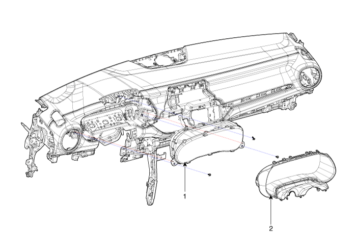
1. Instrument cluster
2. Cluster fascia panel

Schematic diagrams
Connector and Terminal function
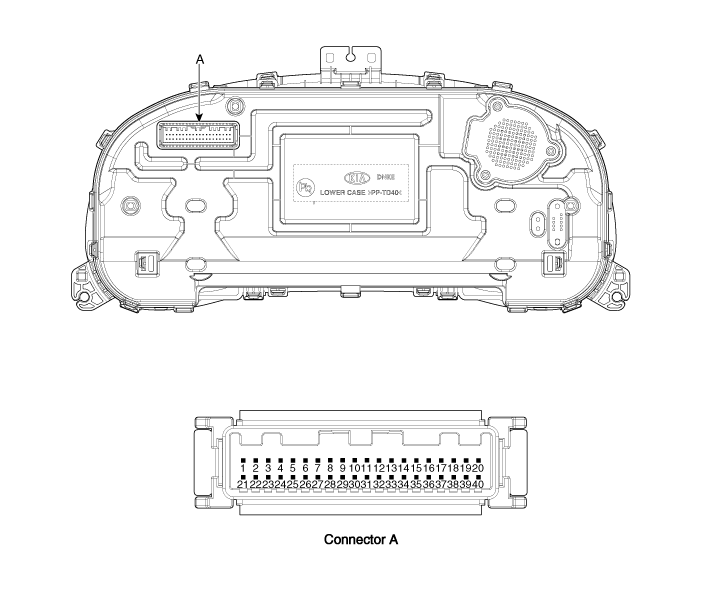
No.
Description
No.
Description
1
Ground
21
Trip switch (-)_Input
2
Illumination (-)
22
Trip switch 1 (+)_Input
3
Rheostat switch (Down)_Input
23
Trip switch 2 (+)_Input
4
Rheostat switch (Up)_Input
24
Active ECO switch_Input
5
Detent
25
Drive mode switch_Input
6
AT ('P' Position)
26
MT ('R' Position)
7
AT ('R' Position)
27
-
8
AT ('N' Position)
28
Washer level low signal
9
AT ('D' Position)
29
B-CAN (Low)
10
AT ('S' Position)
30
B-CAN (High)
11
Immobilizer_Input
31
Alternator_Output (Gasoline only)
12
Vehicle speed_Output
32
C-CAN (High)
13
Alternator_Input (Gasoline only)
33
C-CAN (Low)
14
Fuel sender (+)_Input
34
Ambient temperature_Input
15
Vehicle speed_Input
35
FFV 5V_Output (+)
LPI Fuel_Input
16
Fuel sender (-)_Input
36
Steering heater indicator_Input
17
Water separator_Input (Diesel only)
37
Ground
18
Air bag (+)_Input
38
LDC (Battery +)_Input
19
Oil press switch_Input (Gasoline only)
39
IGN1
20
Tail lamp_Input
40
Battery (+)

Repair procedures
Removal
  

When prying with a flat-tip screwdriver or use a prying trim tool, wrap it with protective tape, and apply protective tape around the related parts, to prevent damage.
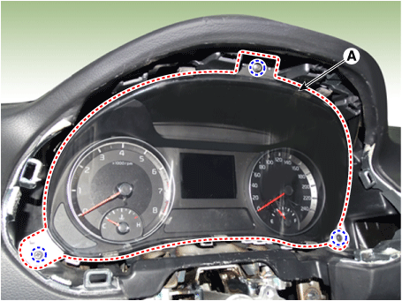
1.

Disconnect the negative (-) battery terminal.

2.

Remove the cluster fascia panel.

(Refer to Body - "Cluster Fascia Panel")

3.

Remove the instrument cluster (A) after loosening the screws.
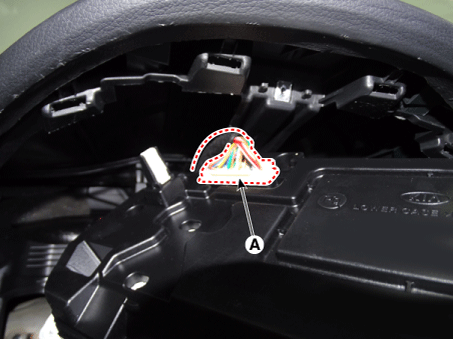
4.

Disconnect the connector (A) from instrument cluster.

Installation
1.

Install in the reverse order of removal.

2.

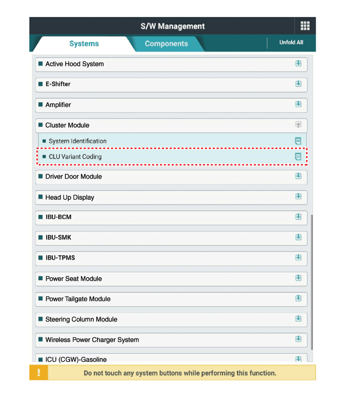
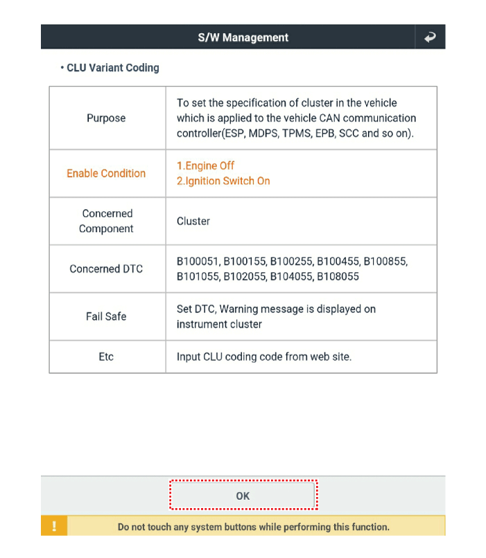
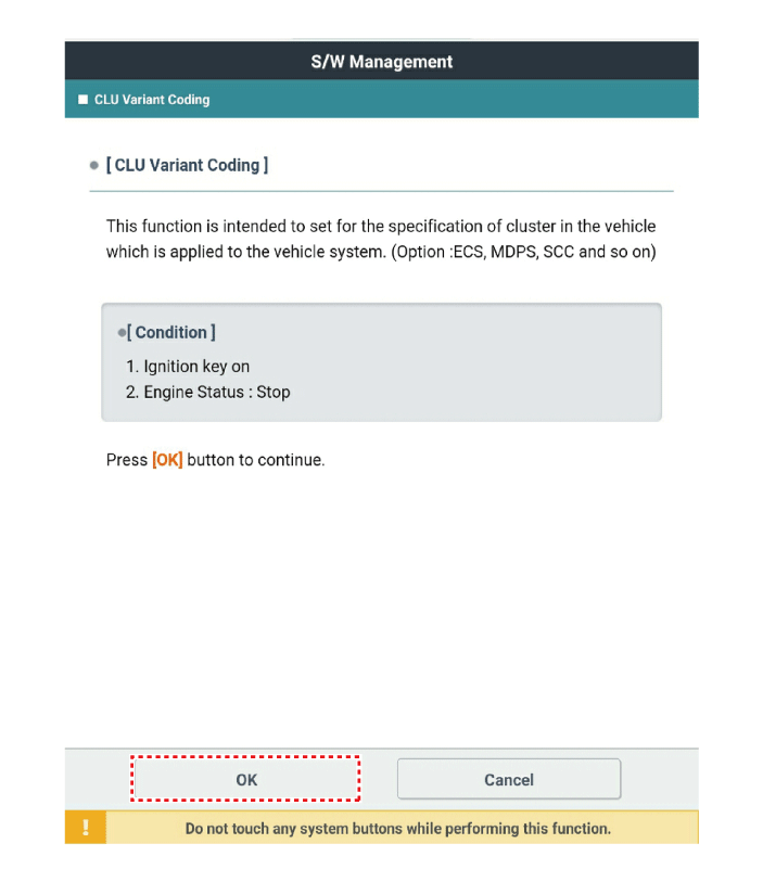
After replacing the cluster with a new one, the "Variant Coding" procedure must be performed.

Inspection
1.

Check point (Warning indicator)


For fault conditions and normal operating conditions, refer to the owner's manual.

NO
Ref Symbol
Name
Color
Signal input
Signal Control
Check point
1

Turn signal (Left)
Green
CAN
IBU
(Gateway)
1) Multifunction Switch
2) IBU
3) CAN Failure
2

Turn signal (Right)
Green
CAN
IBU
(Gateway)
1) Multifunction Switch
2) IBU
3) CAN Failure
3

Tail Lamp
Green
CAN
IBU
(Gateway)
1) Multifunction Switch
2) IBU
3) CAN Failure
4

Front Fog Lamp
Green
CAN
IBU
(Gateway)
1) Multifunction Switch
2) IBU
3) CAN Failure
5

Rear Fog Lamp
Yellow
CAN
IBU
(Gateway)
1) Multifunction Switch
2) IBU
3) CAN Failure
6

High Beam
Blue
CAN
IBU
(Gateway)
1) Multifunction Switch
2) IBU
3) CAN Failure
7

Low Beam
Green
CAN
IBU
(Gateway)
1) Multifunction Switch
2) IBU
3) CAN Failure
8

HBA
Green
CAN
LDWS
1) LDWS System
2) CAN Failure
9

Warning
Yellow
CAN
BSD
1) BSD System
2) CAN Failure
TPMS
1) TPMS System
2) CAN Failure
SCC
1) SCC System
2) CAN Failure
LDWS
1) LDWS System
2) CAN Failure
FCW
1) FCW System
2) CAN Failure
HBA
1) HBA System
2) CAN Failure
IBU
1) Exterior Lamp
2) IBU
3) CAN Failure
Hard-wired
Low Washer
1) Washer fluid lever sensor
2) Wiring Failure
Digital Input
Reminder for service checks
10

Battery Charge
Red
Hard-wired
Alternator
1) Alternator
2) Wiring Failure
3) Battery
11

Oil Pressure
Red
Hard-wired
ECM
1) Oil Pressure Sensor
2) Wiring Failure
3) ECM
4) CAN Failure
12

Check Engine
Yellow
CAN
ECM
1) ECM
2) CAN Failure
13

Immobilizer
Yellow
CAN
+
Hard-wired
IMMOBILIZER
SMK
1) Immobilzer System
2) SMK
3) IBU
4) CAN Failure
5) Hard-wired
14

Parking Brake
Brake Fluid
EBD
EPB
EVP
Red
CAN
IBU
(Gateway)
EBD
EPB
EVP
ABS
TCS
1) IBU
2) ABS System
3) EPB System
4) CAN Failure
5) Parking Brake Switch
6) Brake Oil Lever Sensor
15

ABS
Yellow
CAN
ABS
1) ABS System
2) CAN Failure
16

ESC
Yellow
CAN
TCS
1) ABS System
2) CAN Failure
17

ESC Off
Yellow
CAN
TCS
1) ABS System
2) CAN Failure
18

EPB
Yellow
CAN
EPB
1) EPB System
2) CAN Failure
19

Auto Hold
White
Yellow
Green
CAN
TCS
1) TCS System
2) CAN Failure
20

Seat Belt
Red
CAN
IBU
(Gateway)
1) IBU
2) CAN Failure
21

Airbag
Red
CAN
SRSCM
1) SRSCM System
2) CAN Failure
22

EPS
(MDPS)
Red
CAN
MDPS
1) MDPS Unit System
2) MDPS Motor
3) CAN Failure
23

TPMS
Yellow
CAN
TPMS
1) TPMS System
2) TPMS Sensor
3) CAN Failure
24

LDWS
Green
Yellow
White
CAN
LDWS
1) LDWS System
2) CAN Failure
25

Fuel Warning
Yellow
Direct
(Micom)
Fuel Sender
1) Fuel Sender Failure
2) Wiring Failure
26

ECO
Green
Hard-wired
ECO Mode
1) Drive Mode Switch
2) ECM System
3) TCU System
27

SPORT
Yellow
Hard-wired
SPORT Mode
1) Drive Mode Switch
2) ECM System
3) TCU System
28

CRUISE
Green
CAN
ECM
1) ECM
2) CAN Failure
29

SET
Green
CAN
ECM
1) ECM
2) CAN Failure
30

Water seperator
Red
Hard-wired
Water seperator sensor
1) Water seperator sensor
2) Wiring failure
31

GLOW
Yellow
CAN
ECM
1) ECM
2) CAN Failure
32

Diesel Particulate Filter (DPF)
Yellow
CAN
ECM
1) DPF System
2) CAN Failure
33

Oil Level
Yellow
CAN
ECM
1) ECM
2) CAN Failure
34

AEB
Yellow
CAN
SCC
1) AEB System
2) CAN Failure
35

AUTO STOP
Green
Yellow
CAN
ECM
1) ECM
2) CAN Failure
36

Over Speed Warning
Yellow
CAN
ABS
TCS
(Speed)
1) ABS System
2) TCS System
3) CAN Failure

2.

Check point (Gauge)

NO
Name
Signal Input
Signal Control
(Unit/Sensor)
Check Point
1
Speedometer
C-CAN
ABS/ESC
1) CAN Line failure
3
Tachometer
C-CAN
EMS
1) CAN Line failure
4
Cooling water temperature
C-CAN
EMS
1) CAN Line failure
5
Fuel
Hardwire
Fuel Sander
1) Fuel sender failure
2) Wiring failure
6
Shift lever indicator
C-CAN
TCU
1) CAN Line failure

Diagnosis with KDS

1.

In the body electrical system, failure can be quickly diagnosed by using the vehicle diagnostic system (KDS).

The diagnostic system (KDS) provides the following information.

(1)

Self diagnosis : Checking failure and code number (DTC)

(2)

Current data : Checking the system input/output data state

(3)

Actuation test : Checking the system operation condition

(4)

Additional function : Controlling other features including system option setting and zero point adjustment

2.

Select the 'Car model' and the 'Cluster Module (CLU)' to be checked in order to check the vehicle with the tester

3.

Select the 'Current Data' menu to search the current state of the input/output data.

The input/output data for the sensors corresponding to the cluster module (CLU) can be checked.

4.

To forcibly actuate the input value of the module to be checked, select option 'Actuation Test'

Indicators And Gauges
Troubleshooting Troubleshooting Error Item Failure symptom Inspection items Detailed inspections Relevant Parts/ Componen ...

Integrated Body Control Unit (IBU)
Specifications Specifications Items Specifications Rated voltage DC 12 V Operating voltage DC 9 - 16 ...

Other information:

Kia Forte 2019-2024 (BD) Owners Manual: Windshield defrosting and defogging


WARNING - Windshield heating Do not use the or position during cooling operation in extremely humid weather. The difference between the temperature of the outside air and the windshield could cause the outer surface of the windshield to fog up, causing loss of visibility. In t ...

Kia Forte 2019-2024 (BD) Service Manual: Blind-Spot Radar


Specifications Specifications Items Specification Rated voltage DC 12 V Operating voltage 9 - 16 V Operating speed 30 - 255 km/h Sensing distance ...

Copyright © www.kiforte.com 2017-2024