Kia Forte: Dual Clutch Transmission Control System / Input Speed Sensor 1
Components and components location
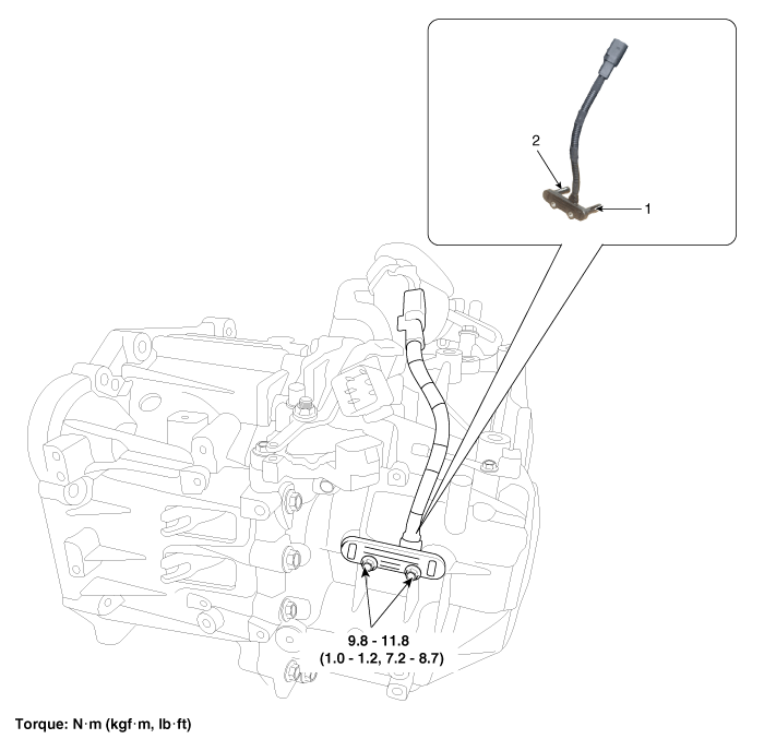
1. Input shaft speed sensor 1
(Odd)
|
2. Input shaft speed sensor 2
(Even)
|
Specifications
Item
|
Specification
|
Type
|
Hall effect sensor
|
Operating condition
|
-40 to 302°F (-40 to 150°C)
|
Output signal
|
High: 11.8 - 16.8 mA
|
Low: 5.9 - 8.4 mA
|
Description and operation
| • |
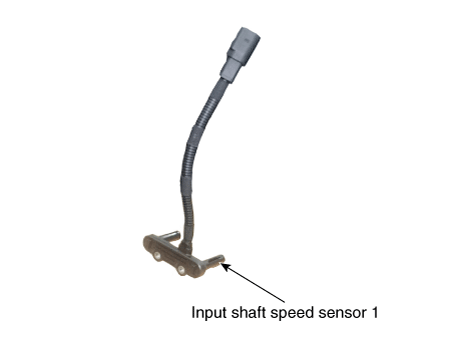
The input shaft speed sensor is important in that it detects the input
shaft RPM and sends this information to the Transmission Control Module
(TCM).
|
| • |
This data is necessary for all operations including feedback control,
gear shift control and failure detection of other sensors.
|
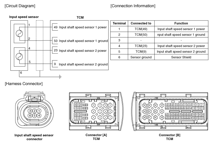
Schematic diagrams
Repair procedures
| 1. |
Remove the clutch actuator.
(Refer to Dual Clutch Transmission Control System - "Clutch Actuator
Assembly")
|
| 2. |
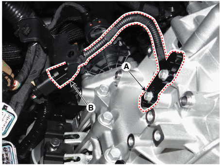
Remove the input speed sensor (A) by loosening the bolts after disconnecting
the connector (B).
|
Tightening torque :
9.8 - 11.8 N·m (1.0 - 1.2 kgf·m, 7.2 - 8.7 lb·ft)
|
|
| 1. |
Install in the reverse order of removal.
|
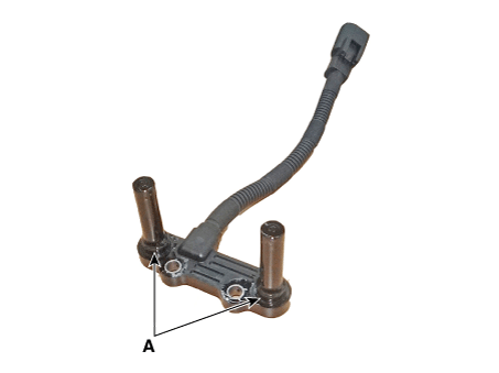
Before installing the input speed sensor, check the assembled
state of the O-rings (A) and apply gear oil to the surface of O-rings.
|
|
Components and components location
Component Location
1. Gear actuator assembly
2. Shift motor (Even)
3. Shift motor (Odd)
4. Select solenoid (Even)
5. S ...
Components and components location
Component Location
1. Input shaft speed sensor 1
(Odd)
2. Input shaft speed sensor 2
(Even)
Specification ...
Other information:
Components and components location
Components
[Couple torsion beam axle type]
1. Rear wheel speed sensor connector
2. Rear wheel speed sensor
[Multi link type]
1. Rear wheel speed sensor connector
2. ...
Repair procedures
Removal and Installation
Do not disassemble the oil pump (A) from timing chain cover because it
is supplied as timing chain cover & oil pump assembly.
...


 Gear Actuator Assembly
 Input Speed Sensor 2


