Kia Forte: Body Electrical System / Horn
Specifications
| Specifications |
|
Items |
Specifications |
Remark |
|
Operating voltage |
9 - 16 V |
- |
|
Current consumption |
MAX 5.0 A |
At 12 V |
|
Sound level |
110 ± 3 dB |
At 13 V, 2 m |
|
Insulation resistance |
MIN 1 MΩ |
By 500 V megarmeter |
Components and components location
| Components |
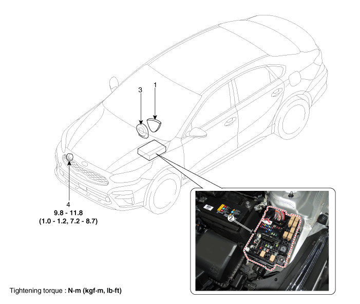
| 1. Horn switch 2. Horn relay (Built - in Metal Core Block PCB) |
3. Clock spring 4. Horn |
Repair procedures
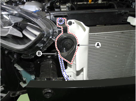
| Removal |
| 1. |
Remove the front bumper assembly. (Refer to Body - "Front Bumper Assembly") |
| 2. |
Remove the horn (A) by loosening the bolt after disconnecting the connector (B).
|
| Installation |
| 1. |
Install in the reverse order of removal. |
| Inspection |
| 1. |
The relay on the horn of this vehicle is implanted into the metal core block PCB of the engine room relay block. |
The semi-conductor type relay inserted in the PCB is impossible to replace. If the relay needs to be replaced, replace the metal core box and conduct a test on it. |

 Headlamp Leveling Switch (Manual)
Schematic diagrams
Circuit Diagram
Repair procedures
Removal
1.
Disconnect the negative (-) battery terminal.
2.
Remove the crash ...
 Ignition Switch Assembly
Repair procedures
Removal
1.
Disconnect the negative (-) battery terminal.
2.
Remove the crash pad lower panel.
(Refer to Body - "Crash Pad ...
Other information:
Kia Forte 2019-2025 (BD) Service Manual: Fuel Delivery System
Components and components location Components Location Fuel Tank & Filler-Neck Assembly 1. Fuel Tank 2. Fuel Pump 3. Fuel Pump Plate Cover 4. Fuel Filler Hose 5. Leveling Tube 6. Vapor port [Fuel pump (Canister) → Intake Manifold] ...
Kia Forte 2019-2025 (BD) Service Manual: Crash Pad
Components and components location Components Components (1) 1. Fuse box cover 2. Crash pad side switch 3. Crash pad lower panel 4. Steering column lower shroud cover 5. Crash pad side cover [LH] 6. Crash pad assembly 7. Crash pad side cover ...
Copyright © www.kiforte.com 2017-2025
