Kia Forte: Heating, Ventilation and Air Conditioning / Heater & A/C Control Unit (DATC)
Components and components location
| Components |
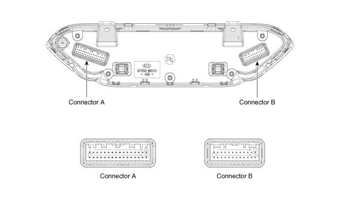
[Connector A]
|
Pin NO |
Function |
Pin NO |
Function |
|
1 |
Battery (+) |
17 |
IGN2 |
|
2 |
ISG B+ |
18 |
IGN1 |
|
3 |
ILL+ (TAIL) |
19 |
Blower motor (+) |
|
4 |
Sensor ground REF (+5V) |
20 |
HTD (Rear defog indicator) |
|
5 |
Mode control actuator (Feedback) |
21 |
Rear defog switch |
|
6 |
Driver's temperature control actuator (Feedback) |
22 |
Photo sensor (-)_LH |
|
7 |
Intake actuator (Feedback) |
23 |
Photo sensor (-)_RH |
|
8 |
EVAP sensor (+) |
24 |
Detent out (-) |
|
9 |
AMB sensor (+) |
25 |
P_CAN High |
|
10 |
Mode control actuator (Vent) |
26 |
P_CAN Low |
|
11 |
Mode control actuator (Def) |
27 |
FET Drain (Feedback) |
|
12 |
Driver's temperature control actuator (Cool) |
28 |
FET (Gate) |
|
13 |
Driver's temperature control actuator (Warm) |
29 |
ECV + |
|
14 |
Intake actuator (Recirculation) |
30 |
ECV - (Ground) |
|
15 |
Intake actuator (Feedback) |
31 |
Sensor ground |
|
16 |
ILL- (RHEO) |
32 |
Ground |
[Connector B]
|
Pin NO |
Function |
Pin NO |
Function |
|
1 |
Passenger's temperature control actuator (Feedback) |
13 |
PAB On signal |
|
2 |
Passenger's temperature control actuator (Cool) |
14 |
PAB IGN1 |
|
3 |
Passenger's temperature control actuator (Warm) |
15 |
PAB Off signal |
|
4 |
Defogging actuator (Feedback) |
16 |
Auto defogging sensor signal |
|
5 |
Defogging actuator (On) |
17 |
Rear SBR (LH) |
|
6 |
Defogging actuator (Off) |
18 |
SBR |
|
7 |
- |
19 |
Rear SBR (Center) |
|
8 |
- |
20 |
- |
|
9 |
- |
21 |
- |
|
10 |
- |
22 |
- |
|
11 |
Blower relay |
23 |
Rear SBR (RH) |
|
12 |
Blower PWM |
24 |
Ground |
Repair procedures
| Self Diagnosis |
| 1. |
Self-diagnosis process.
|
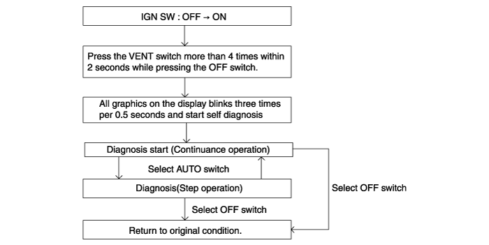

| 2. |
Fault code display
|


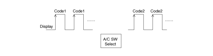
| 3. |
If fault codes are displayed during the check, Inspect malfunction causes by referring to fault codes.
|
| 4. |
Fail safe
|
| Replacement |
| 1. |
Disconnect the negative (-) battery terminal. |
| 2. |
Remove the crash pad center garnish. (Refer to Body - "Crash Pad Center Garnish Assembly") |
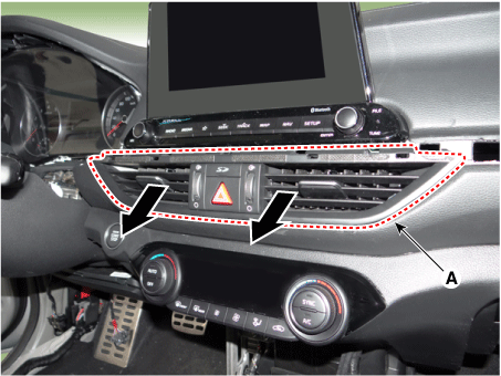
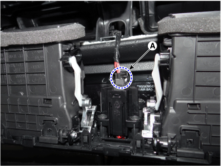
| 3. |
Remove the center facia vent (A).
|
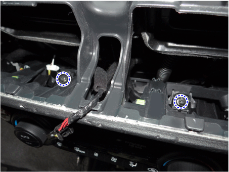
| 4. |
Disconnect the center facia vent connector (A).
|
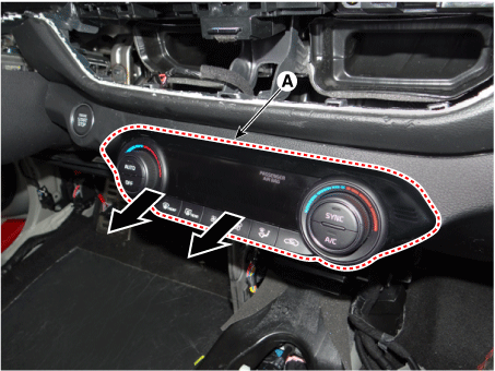
| 5. |
After loosening the mounting screws, remove the A/C & heater controller unit (A).
|
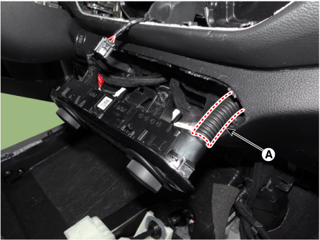
| 6. |
Disconnect the heater controller assembly hose (A).
|
| 7. |
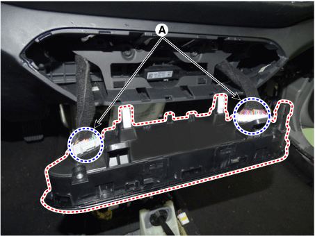
Disconnect the A/C & heater controller connectors (A).
|
| 8. |
To install, reverse the removal procedure.
|
