Kia Forte: Driveshaft Assembly / Front Driveshaft
Components and components location
| Components Location |
| [Gamma 1.6 MPI, Nu 2.0 MPI, New U 1.6 TCI] |
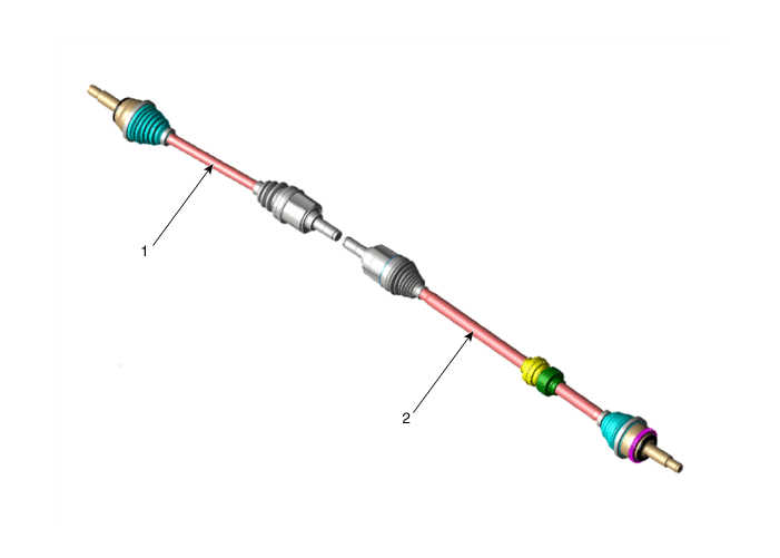
| 1. Drive shaft (LH) |
2. Drive shaft (RH) |
| [Gamma 1.6 T-GDI |
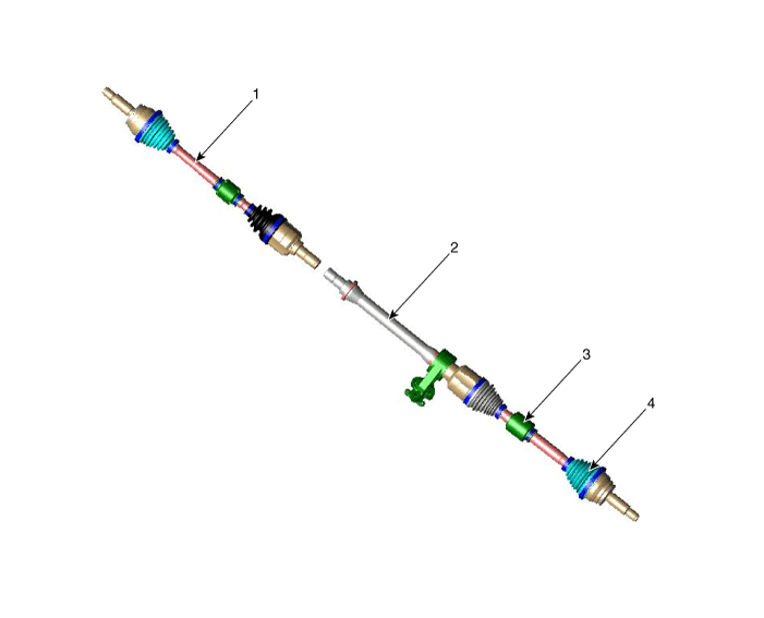
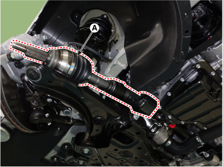
| 1. Drive shaft (LH) 2. Inner shaft bearing brcket |
3. Dynamic damper 4. Drive shaft (RH) |
| [RH] |
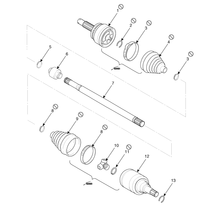
| 1. BJ assembly 2. Clip 3. BJ boot band 4. BJ boot |
5. Dynamic damper band
6. Dynamic damper 7. Shaft 8. TJ boot band |
9. TJ boot
10. Spider assembly 11. Circlip 12. TJ housing |
13. Circlip |
| [LH] |
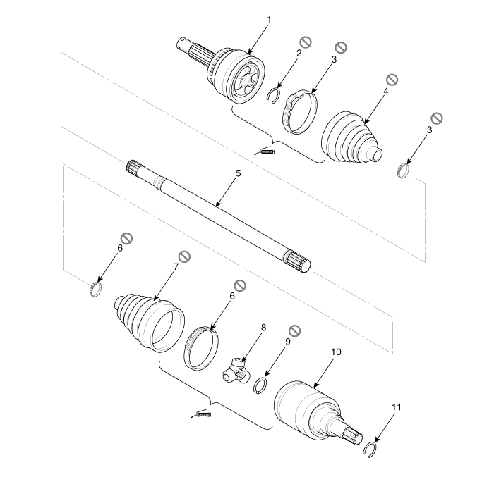
| 1. BJ assembly 2. BJ circlip 3. BJ boot band 4. BJ boot |
5. Shaft 6. TJ boot band 7. TJ boot 8. Spider assembly |
9. Snap
ring 10. TJ case 11. Circlip |
Repair procedures
| Removal and Installation |
| Drive shaft |
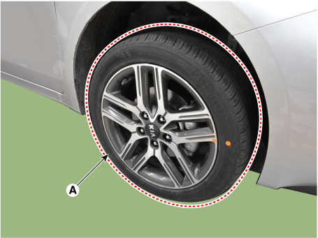
| 1. |
Remove the front wheel and tire (A).
|

| 2. |
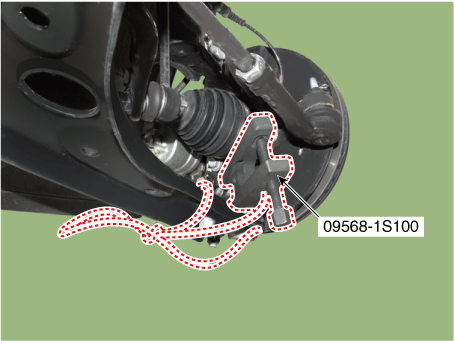
Disconnect the tie rod end ball joint from the knuckle by using the SST (09568-1S100).
|
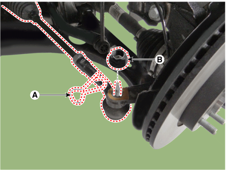
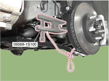
| 3. |
Disconnect the lower arm from the knuckle by using the SST (09568-1S100).
|
| 4. |
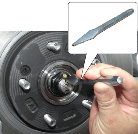
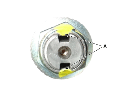
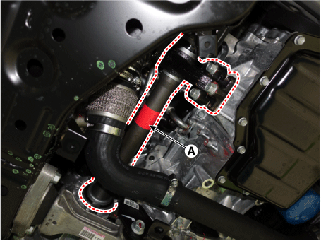
By hammering on a chisel, unlock the driveshaft lock hub nut caulking.
|
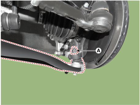
| 5. |
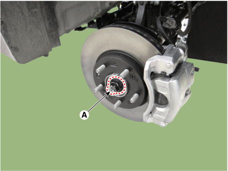
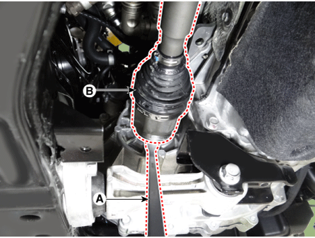
Remove the caulking nut (A) from the front axle.
|
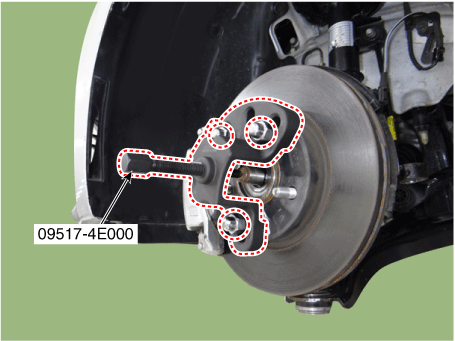
| 6. |
Using a SST (09517-4E000), disconnect the driveshaft from the axle hub.
|
| 7. |
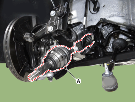
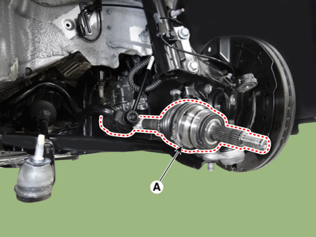
Remove the drive shaft.
|
| 8. |
Install in the reverse order of removal. |
| 9. |
Check the front alignment. (Refer to Suspension System - "Front Alignment") |
Bearing Bracket & Shaft Assembly
| 1. |
Remove the front drive shaft. |
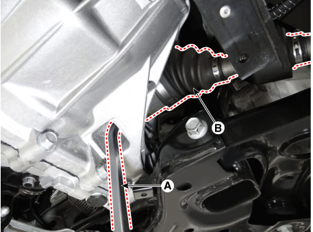
| 2. |
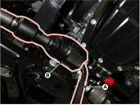
Remove the bearing bracket & shaft assembly (A).
|
| 3. |
Install in the reverse order of removal. |
| 4. |
Check the front alignment. (Refer to Suspension System - "Front Alignment") |

 TJ Joint
Components and components location
Components
[RH]
1. BJ assembly
2. Clip
3. BJ boot band
4. BJ boot
5. Dynamic damper band
6. Dynami ...
Other information:
Kia Forte 2019-2025 (BD) Owners Manual: Special driving conditions
Hazardous driving conditions When hazardous driving conditions are encountered such as water, snow, ice, mud, sand, or similar hazards, follow these suggestions: Drive cautiously and allow extra distance for braking. Avoid sudden braking or steering. When braking with non-ABS br ...
Kia Forte 2019-2025 (BD) Service Manual: Engine Control / Fuel System
Service data Service Data Fuel Delivery System Items Specification Fuel Tank Capacity 50 L (13.2 U.S.gal., 52.8 U.S.qt., 43.9 Imp.qt.) Fuel Filter Type Paper type ...
