Kia Forte: Driveshaft Assembly / TJ Joint
Components and components location
| Components |
| [RH] |
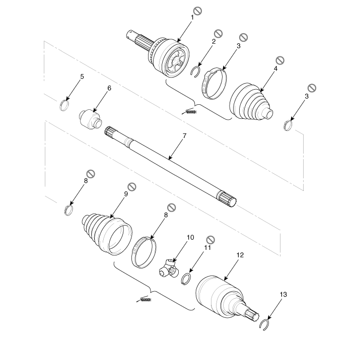
| 1. BJ assembly 2. Clip 3. BJ boot band 4. BJ boot |
5. Dynamic damper band
6. Dynamic damper 7. Shaft 8. TJ boot band |
9. TJ boot
10. Spider assembly 11. Circlip 12. TJ housing |
13. Circlip |
| [LH] |
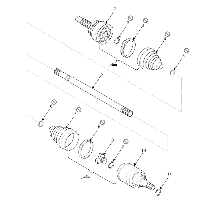
| 1. BJ assembly 2. BJ circlip 3. BJ boot band 4. BJ boot |
5. Shaft 6. TJ boot band 7. TJ boot 8. Spider assembly |
9. Snap
ring 10. TJ case 11. Circlip |
Repair procedures
| Disassembly |
|

| 1. |
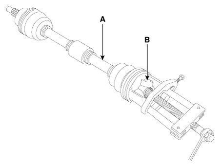
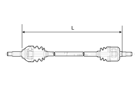
Remove the Front Driveshaft. (Refer to Driveshaft Assembly - “Front Driveshaft”) |
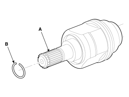
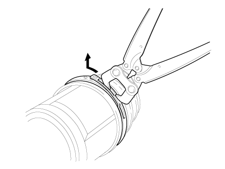
| 2. |
Remove the housing circlip (B) from the driveshaft spline (A).
|
| 3. |
Remove both boot bands from the TJ housing.
|
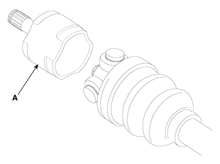
| 4. |
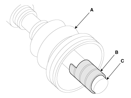
Remove the TJ housing (A).
|
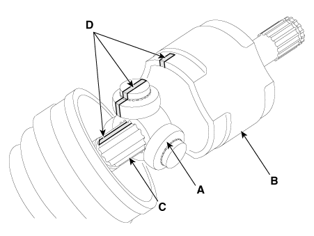
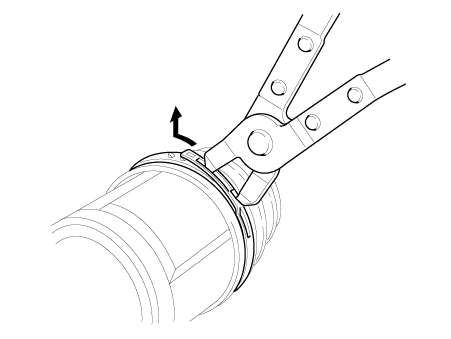
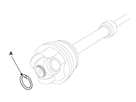
| 5. |
Remove the snap ring (A) from the shaft.
|
| 6. |
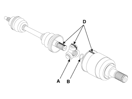
Remove the spider assembly (B) from the driveshaft (A) using the puller.
|
| 7. |
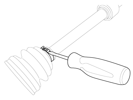
Clean the spider assembly. |
| 8. |
Remove the TJ boot (A).
|
| Inspection |
| 1. |
Check the spider assembly for roller rotation, wear or corrosion. |
| 2. |
Check the groove inside the joint case for wear or corrosion. |
| 3. |
Check the TJ boots for damage and deterioration. |
| Reassembly |
| 1. |
Wrap tape around the driveshaft spline (TJ) to prevent damaging the boot. |
| 2. |
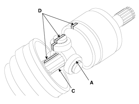
Using the alignment marks (D) made during disassembly as a guide, install the spider assembly (A) and snap ring (B) on the driveshaft splines (C).
|
| 3. |
Add specified grease to the joint boot as much as it was wiped away at inspection. |
| 4. |
Install both boot bands. |
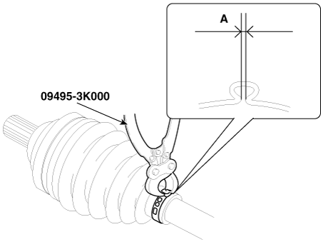
| 5. |
To control the air in the TJ boot, keep the specified distance between the boot bands when they are tightened.
|
|||||||||||||||||||||||||||||
| 6. |
Using the SST (09495-3K000), secure the TJ boot bands.
|
| 7. |
Install the front driveshaft. (Refer to Driveshaft Assembly - “Front Driveshaft”) |
 Front Driveshaft
Components and components location
Components Location
[Gamma 1.6 MPI, Nu 2.0 MPI, New U 1.6
TCI]
1. Drive shaft (LH)
2. Drive shaft (RH)
...
 Dynamic Damper
Components and components location
Components
[RH]
1. BJ assembly
2. Clip
3. BJ boot band
4. BJ boot
5. Dynamic damper band
6. Dynami ...
Other information:
Kia Forte 2019-2025 (BD) Service Manual: MDPS Motor
Repair procedures Replacement • When a DTC related to MDPS motor occurs, check the connectors and wiring. If no problem is found, replace the motor. • ...
Kia Forte 2019-2025 (BD) Service Manual: Keyless Entry And Burglar Alarm
Specifications Specification Item Specification Power source 3 V Operating temperature 14 - 140°F (-10 - 60°C) RF Modulation FSK LF Modulation ...
