Kia Forte: Engine And Transmission Assembly / Engine Mounting
Components and components location
| Components |
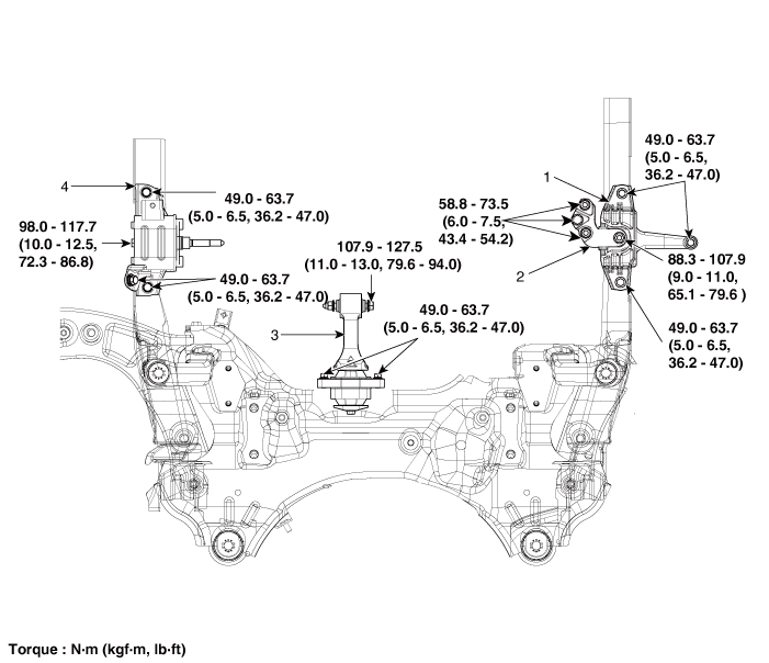
| 1. Engine mounting bracket
2. Engine mounting support bracket |
3. Roll rod bracket 4. Transaxle mounting bracket |
Repair procedures
| Removal and Installation |
Engine Mounting Bracket
| 1. |
Remove the engine room under cover. (Refer to Engine and Transmission Assembly - "Engine Room Under Cover") |
| 2. |
Install the jack to the edge of oil pan to support the engine.
|

| 3. |
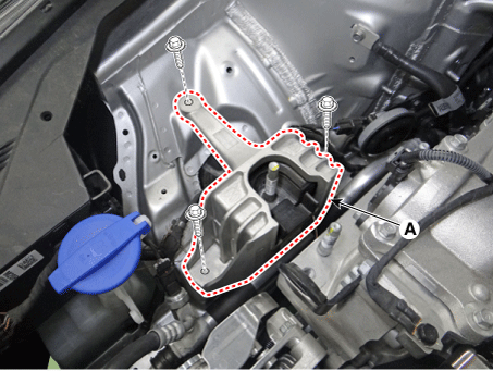
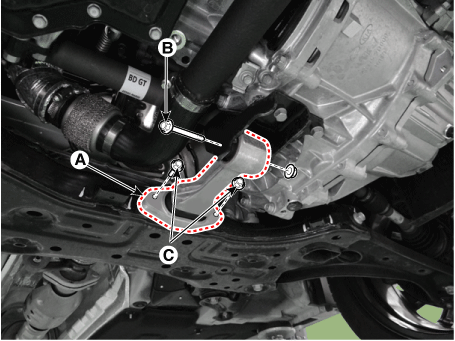
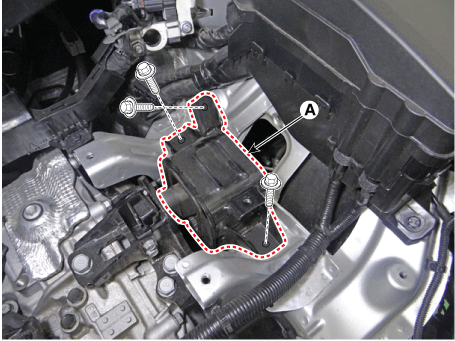
Remove the engine mounting support bracket (A).
|
| 4. |
Separate the reservoir tank to obtain space for remove the engine mounting bracket. (Refer to Cooling System - "Reservoir Tank") |
| 5. |
Remove the engine mounting bracket (A).
|
| 6. |
Install in the reverse order of removal. |
Roll Rod Mounting Bracket
| 1. |
Remove the engine room under cover. (Refer to Engine and Transmission assembly - "Engine Room Under Cover") |
| 2. |
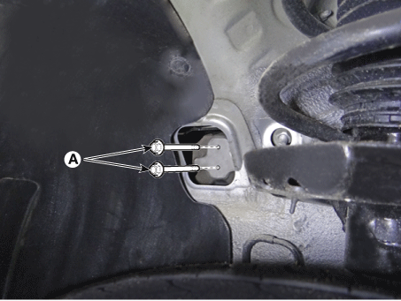
Remove the roll rod bracket (A).
|
| 3. |
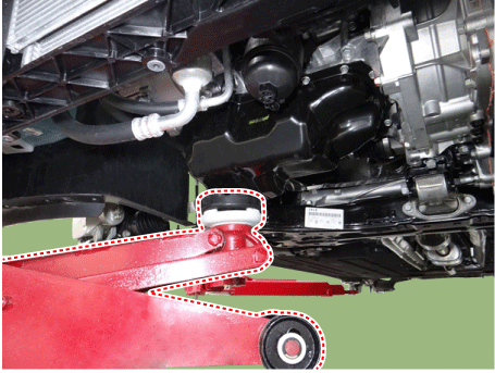
Remove the roll rod support bracket (A).
|
| 4. |
Install in the reverse order of removal. |
Transaxle mounting bracket
| 1. |
Disconnect the battery negative terminal. |
| 2. |
Remove the engine room under cover. (Refer to Engine and Transaxle Assembly - Engine Room Under Cover") |
| 3. |
Remove the air cleaner assembly. (Refer to Intake and Exhaust System - "Air Cleaner") |
| 4. |
Remove the battery and battery tray. (Refer to Engine Electrical System - "Battery") |
| 5. |
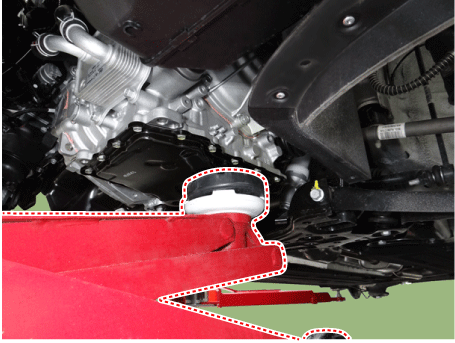
Install jack under the transaxle to support it.
|
| 6. |
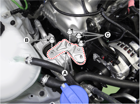
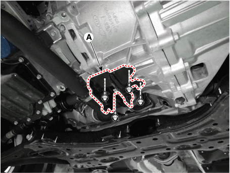
Remove the transaxle mounting side pannel packing (A).
|
| 7. |
Remove the transaxle support bracket mounting bolt (A).
|
| 8. |
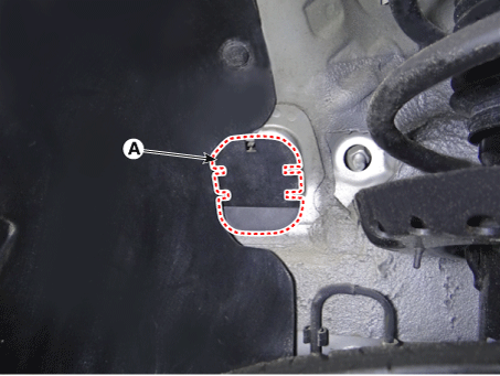
Remove the transaxle mounting bracket (A).
|
| 9. |
Install in the reverse order of removal. |
 Engine Room Under Cover
Repair procedures
Removal and Installation
1.
Remove the engine room under cover (A).
Tightening torque :
3.9 - 5.9 N·m (0.4 - 0.6 kgf·m, 2.9 ...
 Engine And Transmission Assembly
Repair procedures
Removal
•
Use fender covers to avoid damaging painted surfaces.
...
Other information:
Kia Forte 2019-2025 (BD) Service Manual: Idler
Components and components location Components 1. Idler Repair procedures Removal and Installation 1. Remove the drive belt. (Refer to Drive Belt System - "Drive Belt") 2. Remove the idler (A ...
Kia Forte 2019-2025 (BD) Owners Manual: FCA warning message and system control
The FCA system produces warning messages, warning alarms, and emergency braking based on the risk of a frontal collision, such as when a vehicle ahead suddenly brakes. The driver can select the initial warning activation time in the User Settings in the LCD display. The options for th ...
