Kia Forte: Brake System / Vacuum Pump
Components and components location
| Components |
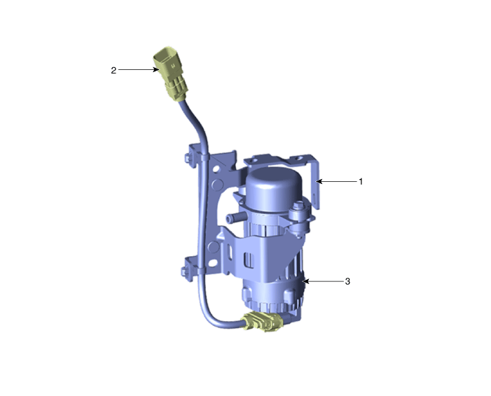
| 1. Vacuum pump bracket 2. Vacuum connector |
3. Vacuum pump |
Schematic diagrams
| Circuit Diagram |
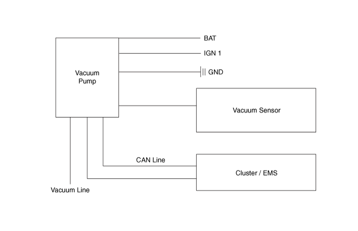
| Terminal Function |

|
PIN No |
Function |
Wire color |
|
1 |
Ground |
BLACK |
|
2 |
CAN High |
WHITE |
|
3 |
CAN Low |
YELLOW |
|
4 |
Vacuum sensor |
PINK |
|
5 |
IGN 1 |
BLUE |
|
6 |
Battery (+) |
BLUE |
Repair procedures
| Removal and Installation |
| 1. |
Disconnect the battery negative terminal. |
| 2. |
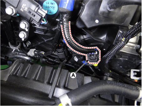
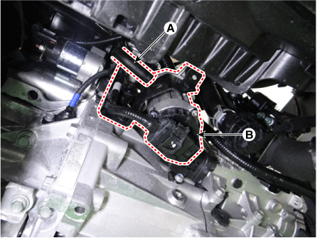
Disconnect the vacuum pump connector (A).
|
| 3. |
Remove the air duct and air cleaner assembly. G 1.6 T-GDI GAMMA (Refer to Engine Mechanical System - "Air Cleaner") |
| 4. |
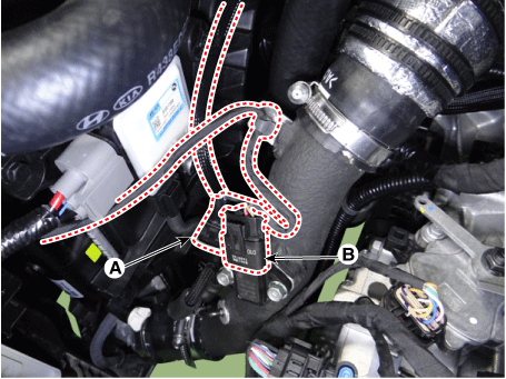
Disconnect the RCV solenoide valve connector (A) and booster pressure sensor (BPS) connector (B).
|
| 5. |
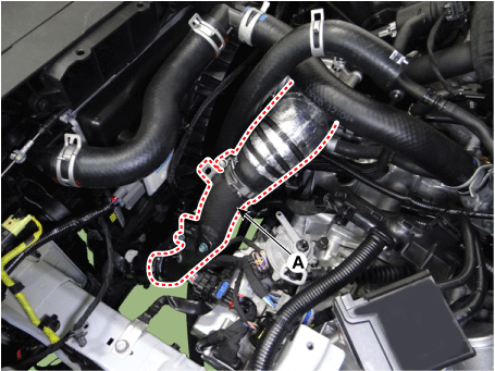
Disconnect the intercooler outlet hose (A).
|
| 6. |
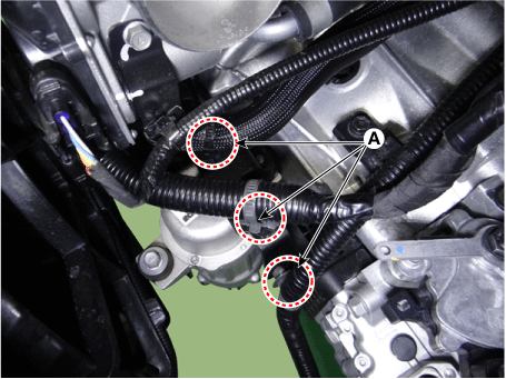
Disconnec the clip (A) from the vacuum pump bracket.
|
| 7. |
Remove the engine room under cover. G 1.6 T-GDI GAMMA (Refer to Engine Mechanical System - "Engine Room Under Cover") |
| 8. |
Disconnect the vacuum hose (A) and then remove the vacuum pump (B).
|
| 9. |
Install in the reverse order of removal. |
 Master Cylinder
Components and components location
Components
1. Reservoir cap
2. Reservoir
3. Reservoir
4. Grommet
5. Master cylinder
Repair procedures
...
 Brake Line
Components and components location
Components
Repair procedures
Removal and Installation
Front
1.
Disconnect the battery negative terminal.
...
Other information:
Kia Forte 2019-2025 (BD) Service Manual: CVVT Oil Control Valve (OCV)
Specifications Specification Item Specification Coil Resistance (Ω) 6.9 - 7.9 [20°C(68°F)] Description and operation Description Continuous Variable Valve Timing (CVVT) system advances or retards the ...
Kia Forte 2019-2025 (BD) Service Manual: Ambient Temperature Sensor
Description and operation Description The ambient temperature sensor is located at the front of the condenser and detects ambient air temperature. It is a negative type thermistor; resistance will increase with lower temperature, and decrease with higher temperature. The sensor o ...
Copyright © www.kiforte.com 2017-2025


