Kia Forte: Power Train / Timing Belt

Kia Forte 2019-2024 (BD) Service Manual / Maintenance / Power Train / Timing Belt

Repair procedures
Inspection
[New U 1.6 TCI]
1.

Remove the engine cover.

(Refer to Engine Mechanical System - "Engine Cover")

2.

Remove the timing belt upper cover.

(Refer to Engine Mechanical System - "Timing Belt Cover")

3.

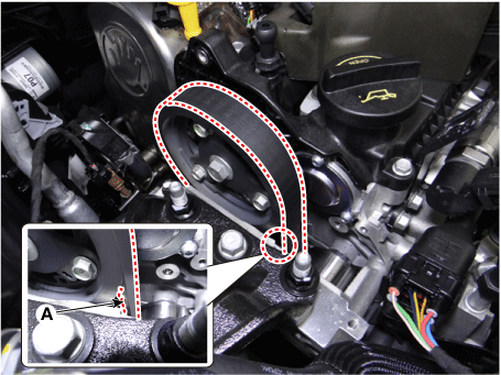
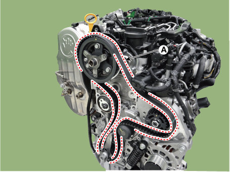
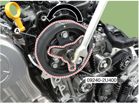
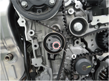
Visuaaly check the timing belt (A) by turning the crankshaft damper pulley bolt clockwise.


If there exists engine oil or coolant on timing belt, replace with new one.

If timing belt is worn or ripped, replace with new one.

4.

Install in the reverse order of removal.

Removal
1.

Disconnect the battery negative terminal.

2.

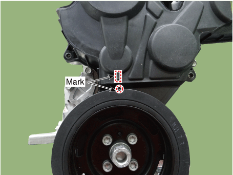
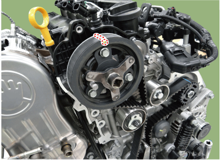
Turn the crankshaft pulley, and align its groove with timing mark "T" of the timing belt cover. (No.1 cylinder compression TDC position)

3.

Remove the engine cover.

(Refer to Engine Mechanical System - "Engine Cover")

4.

Remove the timing belt upper cover.

(Refer to Engine Mechanical System - "Timing Belt Cover")

5.

Remove the drive belt.

(Refer to Engine Mechanical System - "Drive Belt")

6.

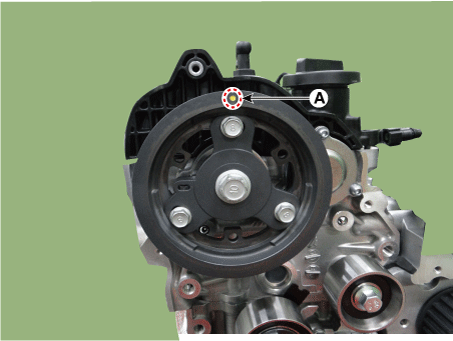
Set the piston of No.1 cylinder to the TDC (top dead center) on compression stroke.

(1)

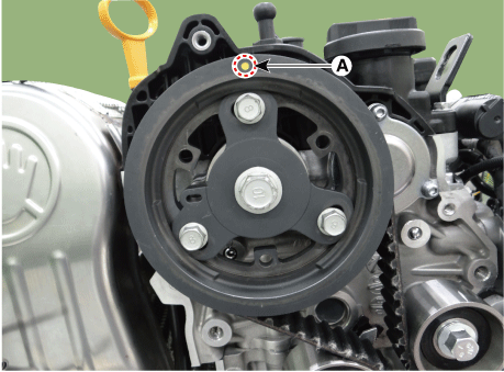
Turn the crankshaft pulley clockwise to position the camshaft sprocket timing mark (A) at the 12 o'clock position.

(2)

Remove the starter motor.

(Refer to Engine Control / Fuel System - "Starter")

(3)

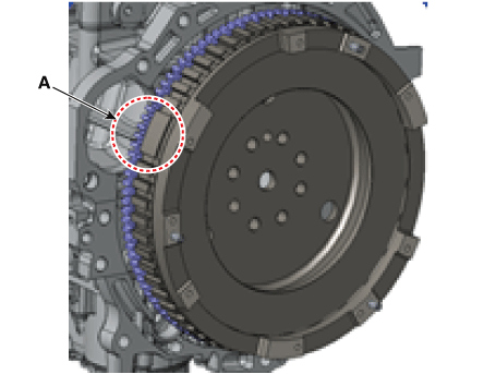
Verify that the flywheel missing tooth (A) is at the ten o'clock position with the starter motor removed.

If not, turn the crankshaft one revolution (360°).

7.

Remove the timing belt lower cover.

(Refer to Engine Mechanical System - "Timing Belt Cover")

8.

Remove the timing belt.

(1)

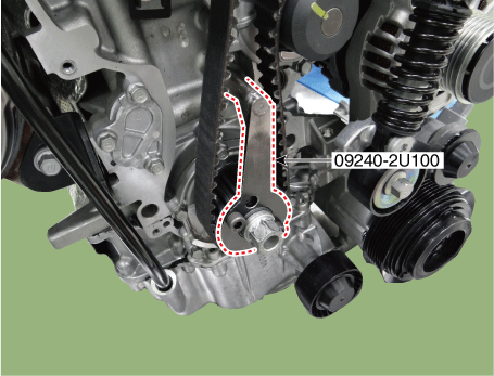
Using the SST (09240-2U100), hold the crankshaft sprocket.

(2)

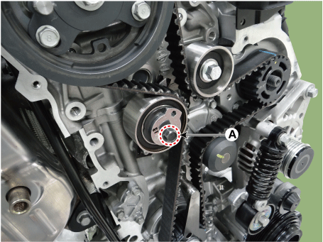
Loosen the bolt (A) on the timing belt tensioner to release the tension.


Do not remove the timing belt tensioner bolt (A).

(3)

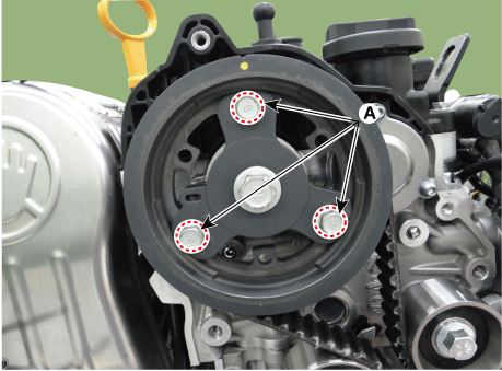
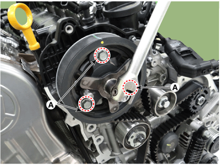
Loosen the bolts (A) on the camshaft sprocket to release the torque.


Do not remove the camshaft sprocket bolts (A).

(4)

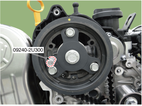
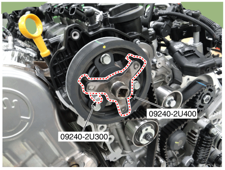
Using the SST (09240-2U300), hold the integrated valvetrain module (IVM) hole.


Make sure install in the integrated valvetrain module hole.

(5)

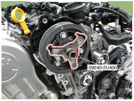
Install the SST (09240-2U400) in the camshaft sprocket.

(6)

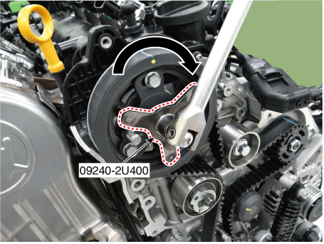
Using the SST (09240-2U400), slightly turn the camshaft sprocket clockwise.

(7)

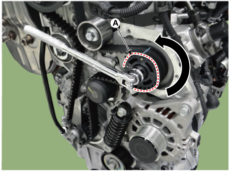
Slightly turn the high pressure fuel pump sprocket (A) counterclockwise to loosen the timing belt on the idler.

(8)

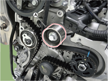
Remove the timing belt idler (A).

(9)

Remove the timing belt (A).

Installation
1.

When reusing the removed timing belt, check if it has three timing marks.

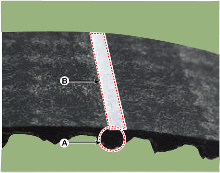
If the timing belt does not have the marks, mark the timing belt with marking paint pen.

(1)

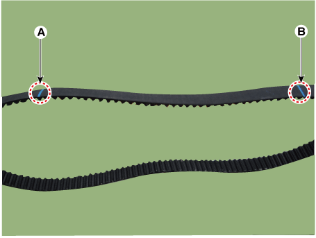
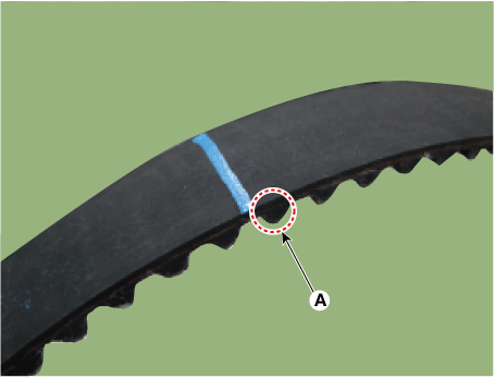
Mark one tooth (A) on the timing belt with marking paint pen to indicate the timing mark (B).

(2)

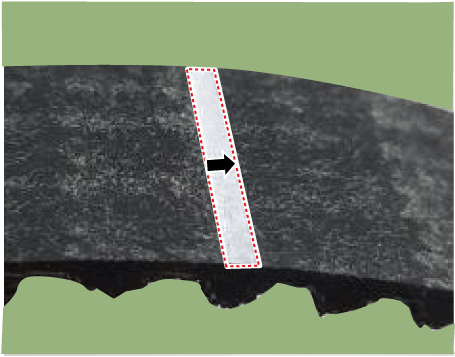
Add an arrow to the timing mark to indicate a starting point.


Timing mark with an arrow is a point where the timing mark on the camshaft sprocket is lined up with the timing mark on the timing belt.

(3)

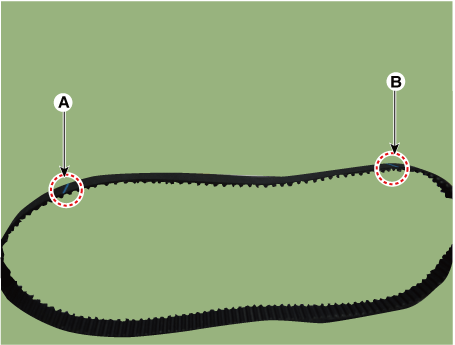
Mark the 36.5th teeth, as counted from the timing mark with an arrow (starting point A), with marking paint pen to indicate the high pressure fuel pump timing mark (B).

Timing belt teeth : 36.5 teeth


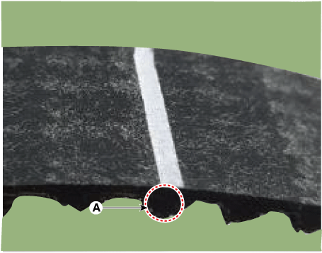
Do not count the marked belt tooth (A).

(4)

Mark the 39.5th teeth, as counted from the high pressure fuel pump timing mark (A), with marking paint pen to indicate the crankshaft timing mark (B).

Timing belt teeth : 39.5 teeth


Count the belt teeth from (A) to 39.5th tooth.

2.

Align the timing mark of the sprockets. As a result of this, the piston of No.1 cylinder is placed at the top dead center on compression stroke.

(1)

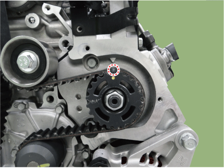
Make sure the camshaft sprocket timing mark (A) at the 12 o'clock position.

(2)

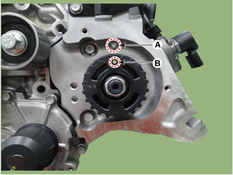
Align the timing mark of the high pressure fuel pump bracket timing mark (A) and high pressure fuel pump sprocket (B).

(3)

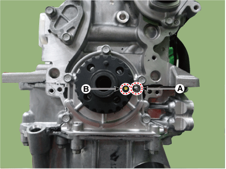
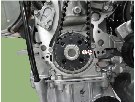
Align the timing mark of the front oil seal cover timing mark (A) and crankshaft sprocket (B).

(4)

Verify that the flywheel missing tooth (A) is at the ten o'clock position.

3.

Install the timing belt (A).


The timing mark of each sprockets should be matched with timing mark of timing belt at installing timing belt as shown below illustration.

[Camshaft sprocket mark]

[High pressure fuel pump sprocket timing mark]

[Crankshaft sprocket timing mark]

4.

Install the idler.

(1)

Slightly turn the camshaft sprocket clockwise by using a SST (09240-2U400).

(2)

Slightly turn the high pressure fuel pump sprocket (A) counterclockwise.

(3)

Install the idler (A).

Tightening torque :

42.2 - 53.9 N·m (4.3 - 5.5 kgf·m, 31.1 - 39.8 lb·ft)

5.

Tighten the camshaft sprocket bolts to specified torque.

(1)

Using the SST (09240-2U400), counterclockwise the camshaft sprocket (A) to the specified torque.

Tightening torque :

34.3 - 44.1 N·m (3.5 - 4.5 kgf·m, 25.3 - 32.5 lb·ft)

(2)

Tighten the camshaft sprocket bolts (A) to specified torque.

Tightening torque :

19.6 - 24.5 N·m (2.0 - 2.5 kgf·m, 14.5 - 18.1 lb·ft)

6.

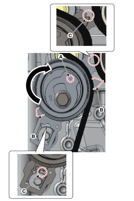
Install the tension of the timing belt.

(1)

Hex head (A) clockwise by using a hexagon wrench and then make sure that the tip of the tensioner indicator (B) is positioned at the center of the half round groove of the base (C).

(2)

Tighten the timing belt tensioner bolt (A) to specified torque.

Tightening torque :

24.5 - 34.3 N·m (2.5 - 3.5 kgf·m, 18.1 - 25.3 lb·ft)

7.

Remove SST from the sprockets.

(1)

Remove the SST(09240-2U100) from the crankshaft sprocket.

Tightening torque :

34.3 - 44.1 N·m (3.5 - 4.5 kgf·m, 25.3 - 32.5 lb·ft)

(2)

Remove the SST (09240-2U300, 09240-2U400) from the camshaft sprocket.

8.

Turn the crankshaft damper pulley bolt clockwise 2 revolutions.

9.

Check the positions of the camshaft sprocket holding pin hole and tensioner indicator.

(1)

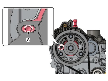
Check the position of the camshaft sprocket holding pin hole (A).

(2)

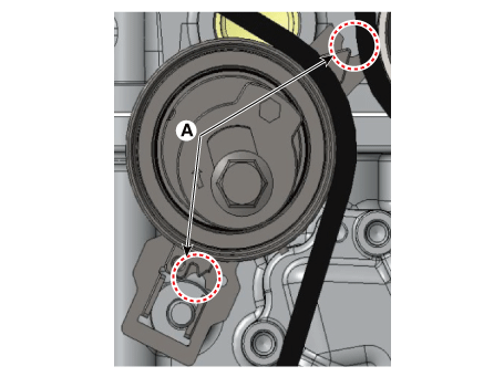
Check the position of the tensioner indicator (A).


If actual camshaft sprocket holding pin hole position does not match the position shown in picture, repeat the steps 6 to 9.

If actual tensioner indicator position does not match the position shown in picture, repeat the steps 6 to 9.

10.

Install in the reverse order of removal

Manual Transaxle Oil
Repair procedures Inspection Manual Transaxle Oil Level Check 1. Uplift the vehicle with lift. 2. Remove the under cover. Nu 2.0 MPI (Refer to E ...

Spark Plug
Repair procedures Inspection [On vehicle inspection] 1. Accelerate the engine to about 3,000 rpm 3 times or more. 2. Remove the spark p ...

Other information:

Kia Forte 2019-2024 (BD) Owners Manual: Securing a child restraint with a lap/shoulder belt


When not using the LATCH system, all child restraints must be secured to a vehicle rear seat with the lap part of a lap/shoulder belt. Automatic locking mode Since all passenger seat belts move freely under normal conditions and only lock under extreme or emergency conditions (emerge ...

Kia Forte 2019-2024 (BD) Owners Manual: Master Warning Mode


• This warning light informs the driver of the following situations: - LED head lamp malfunction (if equipped) - Forward Collision-Avoidance Assist malfunction (if equipped) - Blind-Spot Collision Warning radar blind (if equipped) - Lamp malfunction - High Beam Assist malfunctio ...

Copyright © www.kiforte.com 2017-2024