Kia Forte: Rear Suspension System - Couple Torsion Beam Axle / Rear Shock Absorber
Components and components location
| Components |
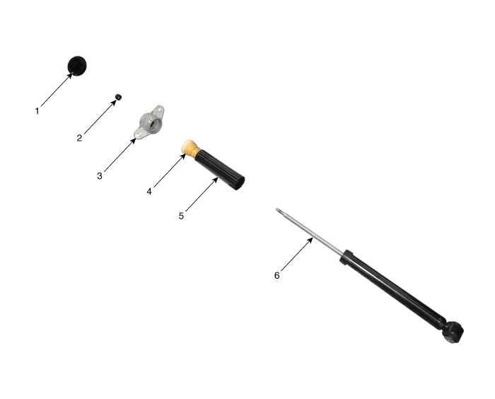
| 1. Shock absorber dust cap
2. Lock nut 3. Insulator assembly |
4. Bumper rubber 5. Dust cover 6. Shock absorber |
Repair procedures
| Removal and Installation |
| 1. |
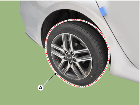
Remove the rear wheel and tire (A).
|
| 2. |
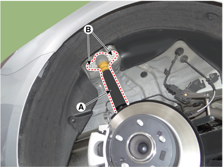
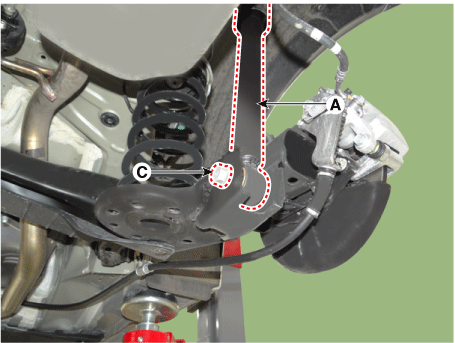
Loosen the bolts and then remove the rear shock absorber (A).
|
| 3. |
Install in the reverse order of removal. |
| Disassembly and Reassembly |
| 1. |
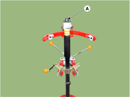
Remove the insulator cap (A).
|
| 2. |
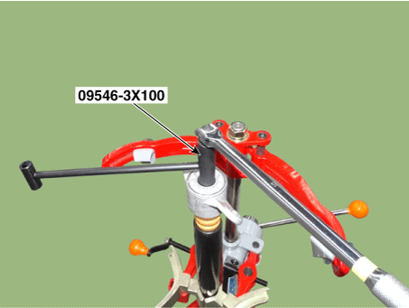
Using the SST (09546-3X100), loosen the self locking nut.
|
| 3. |
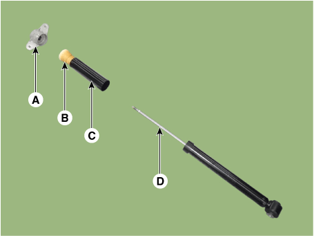
Remove the insulator (A), bumper rubber (B) and dust cover (C) from the shock absorber (D).
|
| 4. |
Reassembly is the reverse of the disassembly. |
| Inspection |
| 1. |
Check the rubber parts for wear and deterioration. |
| 2. |
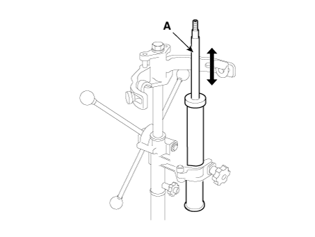
Compress and extend the piston rod (A) and check that there is no abnormal resistance or unusual sound during operation.
|
| 3. |
When installing the rear shock absorber, be sure to hold the upper rod so that the rod is not rotated. |
| Disposal |
| 1. |
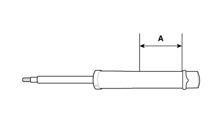
Fully extend the piston rod. |
| 2. |
Drill a hole on the (A) section to remove gas from the cylinder.
|
 Rear Suspension System - Couple Torsion Beam Axle
Components and components location
Components
1. Rear shock absorber
2. Coil spring
3. Torsion beam axle
4. Torsion beam axle cover
...
 Rear Coil Spring
Components and components location
Components
1. Spring upper pad
2. Coil spring
3. Spring lower pad
Repair procedures
Removal and Installat ...
Other information:
Kia Forte 2019-2025 (BD) Service Manual: Tire Pressure Monitoring System
Components and components location Components 1. ESC control module 2. Cluster 3. TPMS SET Switch 4. Wheel speed sensor 5. Tone wheel Description and operation Description Indirect Tire Pressure Monitoring System (TPMS) Using ...
Kia Forte 2019-2025 (BD) Service Manual: Fuel Pressure Control Valve (FPCV)
Specifications Specification Item Specification Coil Resistance (Ω) 0.5 [20°C(68°F)] Description and operation Description Fuel Pressure Control Valve (FPCV) is installed on the high pressure fuel pum ...

