Kia Forte: Engine Control System / Injector
Specifications
Item
|
Specification
|
Coil Resistance (Ω)
|
1.5 ± 0.075 [20°C(68°F)]
|
Description and operation
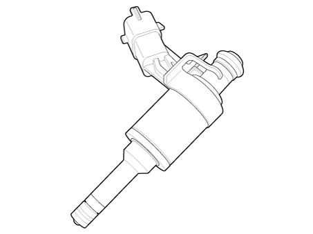
The GDI injector is similar to a standard injector, but sprays fuel at a much
higher pressure directly into the combustion chamber and has a swirl disc to get
the fuel swirling as it exits the nozzle. This aids in atomization of the fuel.The
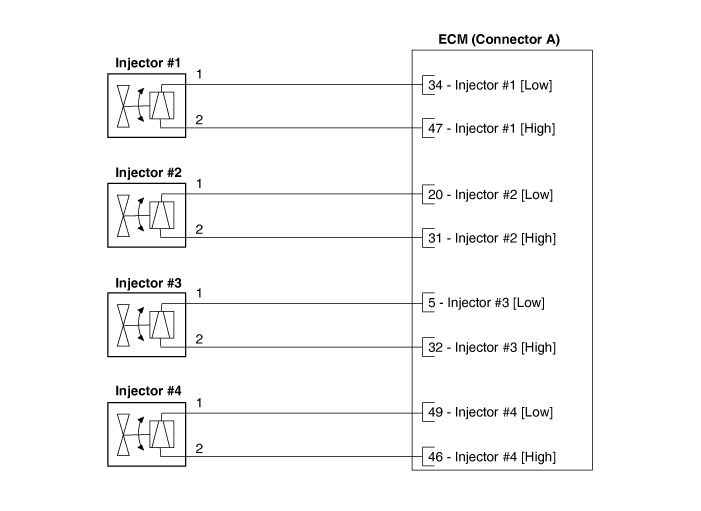
ECM controls both the feed circuits (high side) to feed voltage to the injectors
and the ground circuits (low side) to energize the injectors. Also, the feed for
2 injectors comes from the same driver set. As the ignition coils are paired with
cylinders (1-4 and 2-3), the injectors are also set up in pairs.
Schematic diagrams
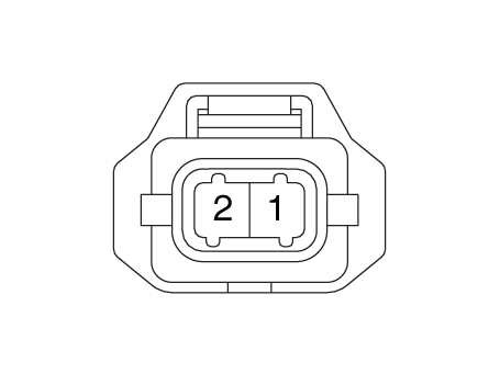
Harness Connector
Repair procedures
| 1. |
Turn the ignition switch OFF.
|
| 2. |
Disconnect the injector connector.
|
| 3. |
Measure resistance between the injector terminals 1 and 2.
|
| 4. |
Check that the resistance is within the specification.
|
Specification: 1.5 ± 0.075 [20°C(68°F)]
|
|
|
In case of removing the high pressure fuel pump, high pressure fuel pipe,
delivery pipe, and injector, there may be injury caused by leakage of the
high pressure fuel. So don’t do any repair work right after engine stops.
|
| 1. |
Turn the ignition switch OFF and disconnect the battery negative (-)
terminal.
|
| 2. |
Release the residual pressure in fuel line.
(Refer to Fuel Delivery System - “Release Residual Pressure in Fuel Line”)
|
| 3. |
Remove the delivery pipe & injector assembly.
(Refer to Fuel Delivery System - "Delivery Pipe").
|
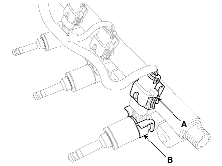
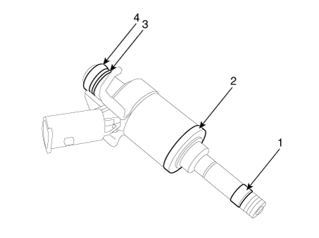
| 4. |
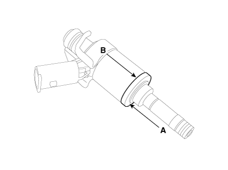
Remove the connector (A) and the fixing clip (B), and then separate the
injector from the delivery pipe.
|
| • |
Do not reuse the used injector fixing clip.
|
| • |
Install the component with the specified torques.
|
| • |
Note that internal damage may occur when the component is dropped.
If the component has been dropped, inspect before installing.
|
| • |
Apply engine oil to the injector O-ring.
|
| • |
Do not reuse the used injector O-ring.
|
| • |
Do not reuse the used bolt.
|
| • |
When inserting the injector, be careful not to damage the injector
tip.
|
| • |
Do not reuse the high pressure fuel pipe.
|
|
| • |
Do not reuse the support disc.
|
| • |
Do not reuse the injector rubber washer.
|
| • |
When replacing the rubber washer, the steal plate (A) part should
be faced the cylinder installation part and the rubber plate (B)
part should be faced the injector body part.
|
|
| • |
Do not reuse the combustion seal.
|
|
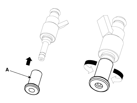
| 1. |
Installation is reverse of removal.
|
The injector combustion seal should be replaced new one to prevent leakage after
removing the injector.
| 1. |
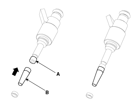
Remove the combustion seal (A) with a wire cutter.
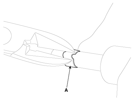
|
Grip the sealing ring carefully, pull it to form a small loop
and then cut it.
Be careful not to damage the surface of the valve sleeve with
the wire cutter.
|
|
| 2. |
Before the assembly of the sealing ring the groove must be cleaned using
a clean cloth.
Any coking of the injector sealing surface must be carefully removed
with a brass-wire brush.
|
The surfaces of the new sealing ring must be clean and free of
grease.
|
|
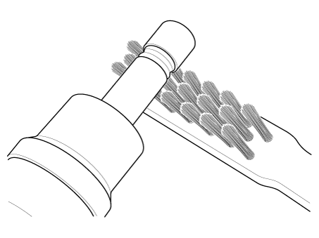
| 3. |
Place the seal installing guide (B) (SST No.: 09353-2B000) on the tip
of the injector not to damage the injector tip (A).
Push the sealing ring (C) with thumb and index finger over the conical
assembly tool until it snaps into the groove.
The complete assembly must not take longer than 2 to 3 seconds.
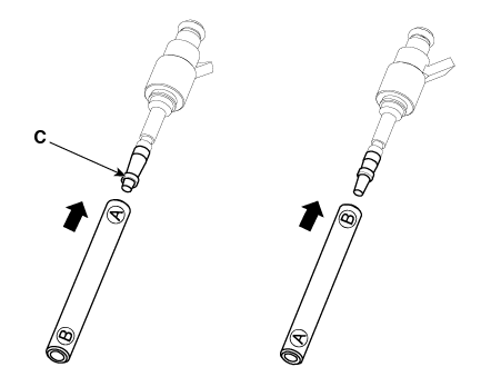
|
| 4. |
To size the sealing ring the injector is first introduced into the sizing
tool (A) (SST No.: 09353-2B000) and then pressed and at the same time rotated
180° into the sizing tool.
|
| 5. |
Pull the injector out of the sizing tool by turning it in the reverse
direction to that used for the press-in process.
|
Check that the seal ring has not been damaged during assembly
to the injector and that no circumferential scratches are present.
Do not reuse the combustion seal.
The seal must be completely free of grease and oil.
|
|
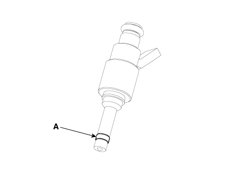
| 6. |
Check the combustion seal (A) installation.
|
Specifications
Specification
Accelerator
Position
Output Voltage (V) [Vref = 5V]
APS1
APS2
C.T
0. ...
Specifications
Specification
Item
Specification
Coil Resistance (Ω)
18.5 - 22.5 [23°C(73.4°F)]
Description and ope ...
Other information:
Repair procedures
Removal
Front Muffler
1.
Disconnect the battery negative terminal.
2.
Disconnect the rear oxygen sensor connector (A).
3.
Remove the front muffler hanger (A).
4.
Remo ...
Repair procedures
Removal
Interior Antenna 1
Take care not to bend or scratch the trim and panels.
1.
Disconnect the negative battery terminal.
2.
Remove the crash pa ...


 Accelerator Position Sensor (APS)
 Purge Control Solenoid Valve (PCSV)