Kia Forte: Dual Clutch Transmission Control System / Inhibitor Switch
Components and components location
| Component Location |
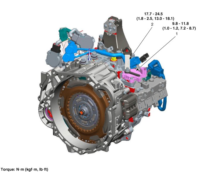
| 1. Inhibitor switch |
2. Manual control lever |
Specifications
| Specification |
|
Item |
Specification |
|
Power supply |
12 V |
|
Output type |
Combination of output signals |
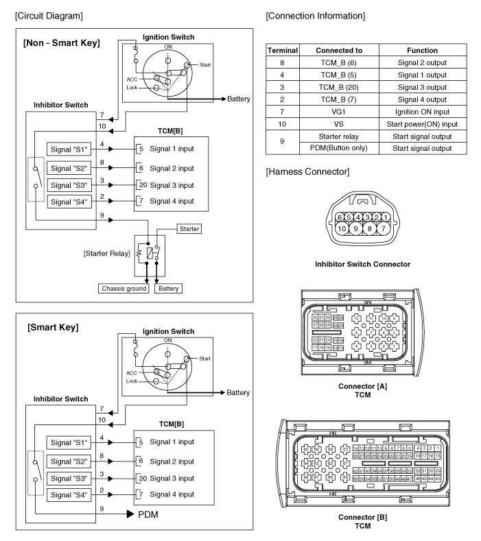
Signal Code Table
|
|
P |
P-R |
R |
R-N |
N |
N-D |
D |
|
Signal "1" |
12 V |
12 V |
0 |
0 |
0 |
0 |
0 |
|
Signal "2" |
0 |
12 V |
12 V |
12 V |
0 |
0 |
0 |
|
Signal "3" |
0 |
0 |
0 |
12 V |
12 V |
12 V |
0 |
|
Signal "4" |
0 |
0 |
0 |
0 |
0 |
12 V |
12 V |
Description and operation
| Description |
| • |
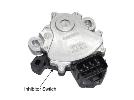
The inhibitor switch is installed on top of transmission, and is connected to the shift lever through shift cable. |
| • |
Inhibitor switch signals (S1, S2, S3, S4) are transmitted to the TCM according to the driver's shift lever control. |
Schematic diagrams
| Circuit Diagram |
Troubleshooting
| Troubleshooting |
Repair procedures
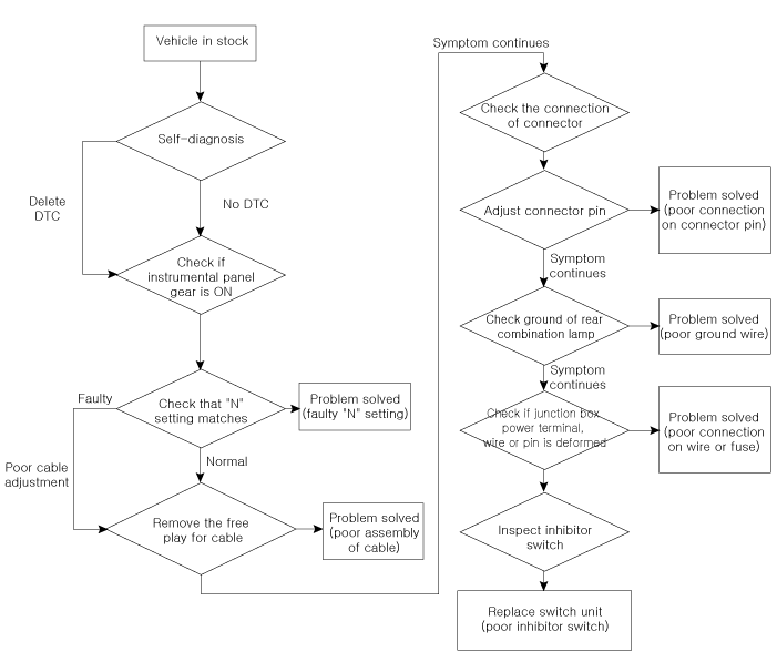
| Inspection |
Inspect the following items by referring to inspection flow chart. (Refer to Inhibitor Switch - "Troubleshooting") |

| 1. |
Check the diagnostic trouble codes (DTC) using KDS. |
| 2. |
Inspect if "N" range setting matches. (Refer to Inhibitor Switch - "Installation") |
| 3. |
Check the free play for shift cable. (Refer to Shift Cable - "Installation") |
| 4. |
Check the condition of connector.
|
| 5. |
Inspect ground condition of rear combination lamp circuit. |
| 6. |
Inspect wiring connection condition of junction box power terminal and fuse lamp.
|
| 7. |
Check the inhibitor switch circuit signal.
Signal Code Table
|
| Removal |
| 1. |
Place the shift lever in the "N" position. |
| 2. |
Remove the air duct and the air cleaner assembly. (Refer to Engine Mechanical System - "Air Cleaner") |
| 3. |
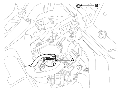
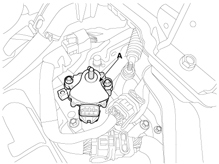
Disconnect the inhibitor switch connector (A). |
| 4. |
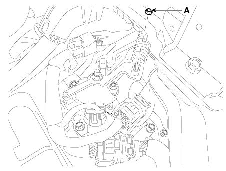
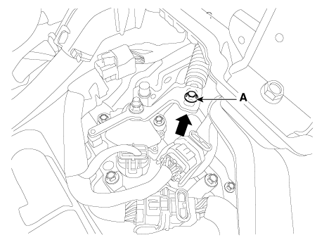
Loosen the shift cable mounting nut (B).
|
| 5. |
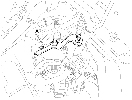
Remove the manual control lever (A).
|
| 6. |
Remove the inhibitor switch (A).
|
| Installation |
| 1. |
Check that the shift lever is placed in the "N" position. |
| 2. |
Install the inhibitor switch (A).
|

| 3. |
Install the manual control lever (A).
|
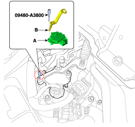
| 4. |
Align the hole (B) in the manual control lever with the "N" position hole (A) of the inhibitor switch and then insert the SST inhibitor switch guide pin (09480-A3800).
|
| 5. |
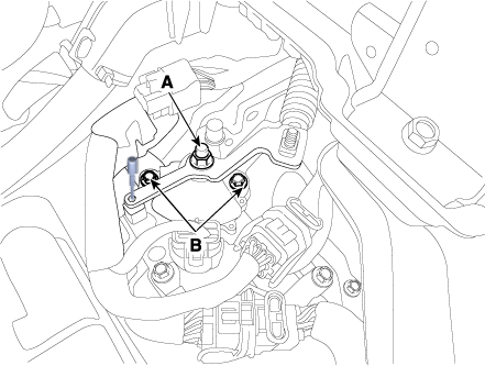
Tighten the manual lever mounting nut (A) to the specified torque.
|
| 6. |
Tighten the inhibitor switch mounting bolts (B) to the specified torque.
|
| 7. |
Remove the SST (09480-A3800) from the adjusment hole. |
| 8. |
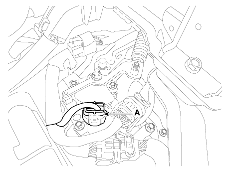
Connect the inhibitor switch connector (A).
|
| 9. |
Tighten the nut (A) loosely.
|
| 10. |
Tighten the nut (A) to the specified torque after removing free play by pushing the shift cable in the direction of the arrow.
|
| 11. |
Install the air duct and air cleaner assembly. (Refer to Engine Mechanical System - "Air Cleaner") |
 Input Speed Sensor 2
Components and components location
Component Location
1. Input shaft speed sensor 1
(Odd)
2. Input shaft speed sensor 2
(Even)
Specification ...
 Shift Lever
Components and components location
Components
1. Shift lever knob & boots
2. Shift lever assembly
3. Shift cable assembly
Repair procedur ...
Other information:
Kia Forte 2019-2025 (BD) Service Manual: Manifold Absolute Pressure Sensor (MAPS)
Specifications Specification Pressure [kPa (kgf/cm², psi)] Output Voltage (V) 32.5 (0.33, 4.71) 0.5 284 (2.90, 41.19) 4.5 Description and operation Description Manifold ...
Kia Forte 2019-2025 (BD) Owners Manual: Transmitter precautions
The transmitter (or smart key) will not work if any of following occurs: The ignition key is in the ignition switch. You exceed the operating distance limit (about 30 m [90 feet]). The battery in the transmitter (or smart key) is weak. Other vehicles or objects may be blockin ...
