Kia Forte: Brake System / Brake Pedal
Components and components location
| Components |
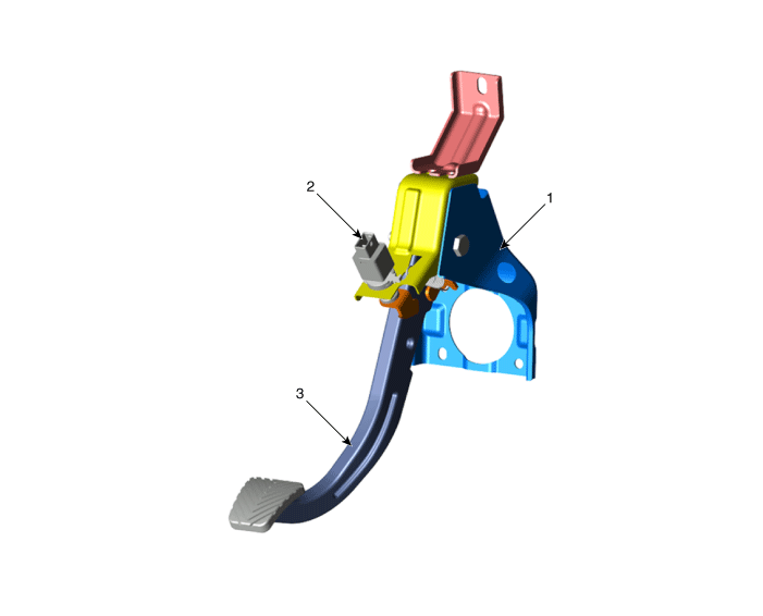
| 1. Brake member assembly 2. Stop lamp switch |
3. Pedal assembly |
Repair procedures
| Removal |
| 1. |
Disconnect the negative battery terminal. |
| 2. |
Remove the crash pad lower panel. (Refer to Body (Interior and Exterior) - "Crash pad lower panel") |
| 3. |
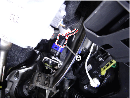
Disconnect the brake switch connector (A).
|
| 4. |
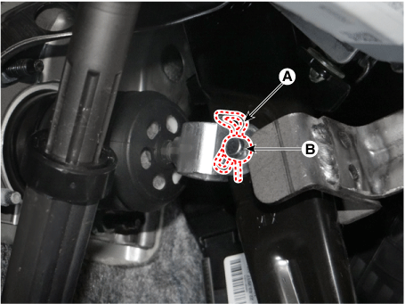
Disconnect the snap pin (A) and clevis pin (B).
|
| 5. |
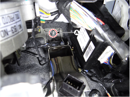
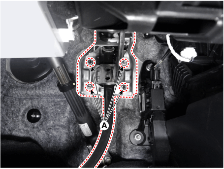
Remove the brake pedal mounting nuts (A).
|
| 6. |
Install in the reverse order of removal |
| Inspection |
| 1. |
Check the bushing for wear. |
| 2. |
Check the brake pedal for bending or twisting. |
| 3. |
Check the brake pedal return spring for damage. |
 Brake Line
Components and components location
Components
Repair procedures
Removal and Installation
Front
1.
Disconnect the battery negative terminal.
...
 Front Disc Brake
Components and components location
Components
1. Caliper body
2. Caliper carrier
3. Brake pad [In]
4. Brake pad [Out]
5. Return spring
6. Pad liner
...
Other information:
Kia Forte 2019-2025 (BD) Service Manual: Steering Column Shroud Panel
Components and components location Component Location 1. Steering column shroud lower panel 2. Steering column shroud upper panel Repair procedures Replacement [Steering column shroud lower panel] &nb ...
Kia Forte 2019-2025 (BD) Owners Manual: Automatic climate control system
1. Driver`s temperature control knob 2. AUTO (automatic control) button 3. Front windshield defroster button 4. Rear window defroster button 5. Air conditioning button 6. Air intake control button 7. Blower OFF button 8. Fan speed control button 9. Mode selection button 10. Passe ...
Copyright © www.kiforte.com 2017-2025


