Kia Forte: Driveshaft and axle / Front Hub / Knuckle
Components and components location
| Components |
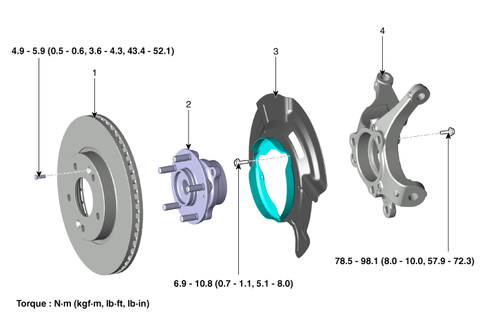
| 1. Front brake disc 2. Front hub bearing |
3. Dust cover 4. Knuckle |
Repair procedures
| Removal and Installation |
| 1. |
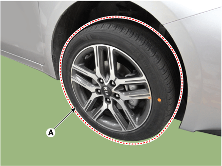
Remove the front wheel and tire (A).
|
| 2. |
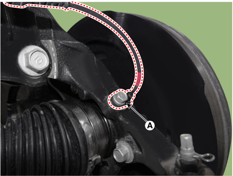
Disconnect the front wheel speed sensor (A).
|
| 3. |
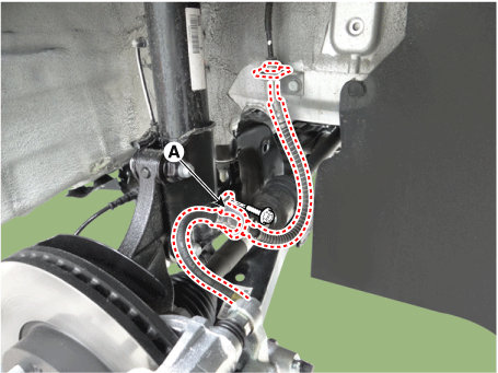
Disconnect the brake hose bracket (A).
|
| 4. |
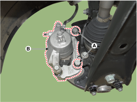
Remove the brake caliper mounting bolts (A), and then hold the brake caliper assembly with wire.
|
| 5. |
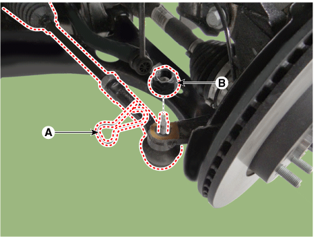
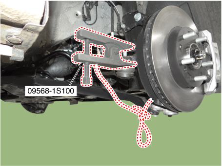
Disconnect the tie rod end ball joint from the knuckle by using the SST (09568-1S100).
|
| 6. |
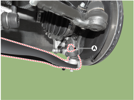
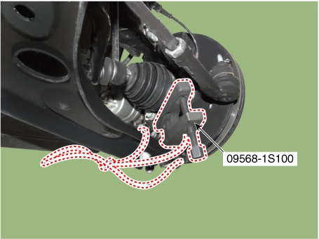
Disconnect the lower arm from the knuckle by using the SST (09568-1S100).
|
| 7. |
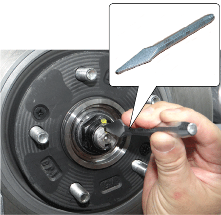
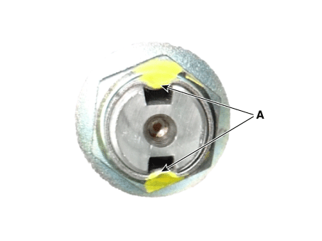
By hammering on a chisel, unlock the driveshaft lock hub nut caulking.
|
| 8. |
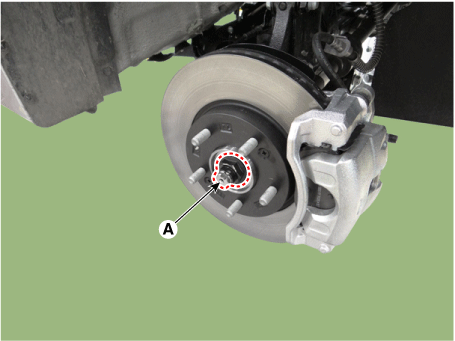
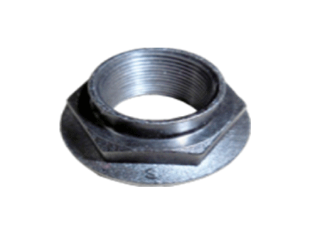
Remove the caulking nut (A) from the front axle.
|
| 9. |
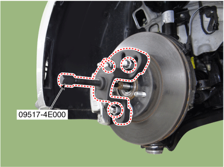
Using a SST (09517-4E000), disconnect the driveshaft from the axle hub.
|
| 10. |
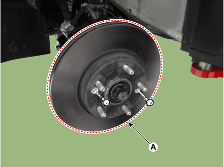
Loosen the screws and then remove the front brake disc (A).
|
| 11. |
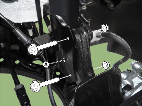
Loosen the front strut (A) bolts and nuts and then remove the knuckle assembly.
|
| 12. |
Install in the reverse order of removal. |
| 13. |
Check the front alignment. (Refer to Suspension System - "Front Alignment") |
| Disassembly |
| 1. |
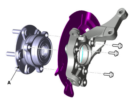
Remove the hub bearing (A) from the knuckle.
|
| 2. |
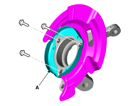
Remove the dust cover (A) from the knuckle.
|
| 3. |
Assemble in the reverse order of disassembly. |
| Inspection |
| 1. |
Check the hub for cracks and the splines for wear. |
| 2. |
Check the brake disc for scoring and damage. |
| 3. |
Check the knuckle for cracks. |
| 4. |
Check the bearing for cracks or damage. |
 Driveshaft and axle
Service data
Service Data
Engine
T/M
Joint type
Max. permissible angle
Outer
Inner
Outer
...
Other information:
Kia Forte 2019-2025 (BD) Owners Manual: Explanation of scheduled maintenance items
Engine oil and filter The engine oil and filter should be changed at the intervals specified in the maintenance schedule. If the vehicle is being driven in severe conditions, more frequent oil and filter changes are required. Drive belts Inspect all drive belts for evidence of cuts, c ...
Kia Forte 2019-2025 (BD) Owners Manual: Engine oil
Checking the engine oil level ■ Nu 2.0L MPI Engine (Gasoline) ■ Gamma 1.6L T-GDI Engine (Gasoline) 1. Be sure the vehicle is on level ground. 2. Start the engine and allow it to reach normal operating temperature. 3. Turn the engine off and wait for a few minutes (about 5 minutes) ...

