Kia Forte: ESC (Electronic Stability Control) System / ESC Control Module
Components and components location
| Components |
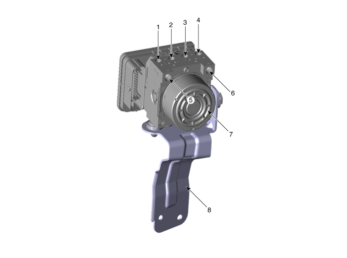
| 1. Front - right tube 2. Rear - left tube 3. Rear - right tube 4. Front - left tube |
5. MC SEC 6. MC PRI 7. ESC control module (HECU) 8. Bracket |
Repair procedures
| Removal |
| 1. |
Turn ignition OFF and disconnect the negative (-) battery cable. |
| 2. |
Remove the brake fluid from the master cylinder reservoir with a syringe.
|
| 3. |
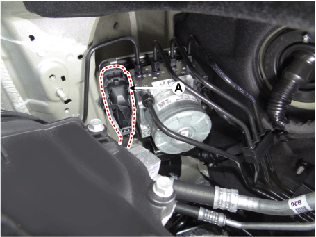
Pull up the lock of the ESC connector (A) and then disconnect the connector.
|
| 4. |
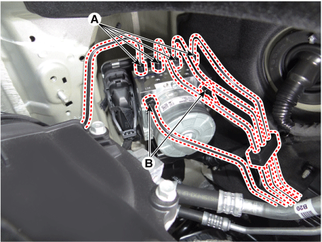
Disconnect the brake tubes from the ECS by unlocking the nuts counterclockwise with a wrench.
|
| 5. |
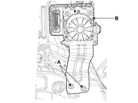
Loosen the ECS bracket nuts (A), then remove ESC and bracket.
|
| Installation |
| 1. |
Install in the reverse order of removal. |
| 2. |
After installation, bleed the brake system. (Refer to Brake system - "Brake Bleeding Prcoedures") |
| 3. |
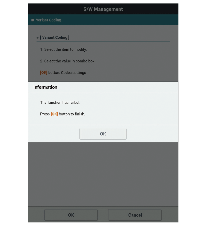
Conduct the Variant coding. |
| 4. |
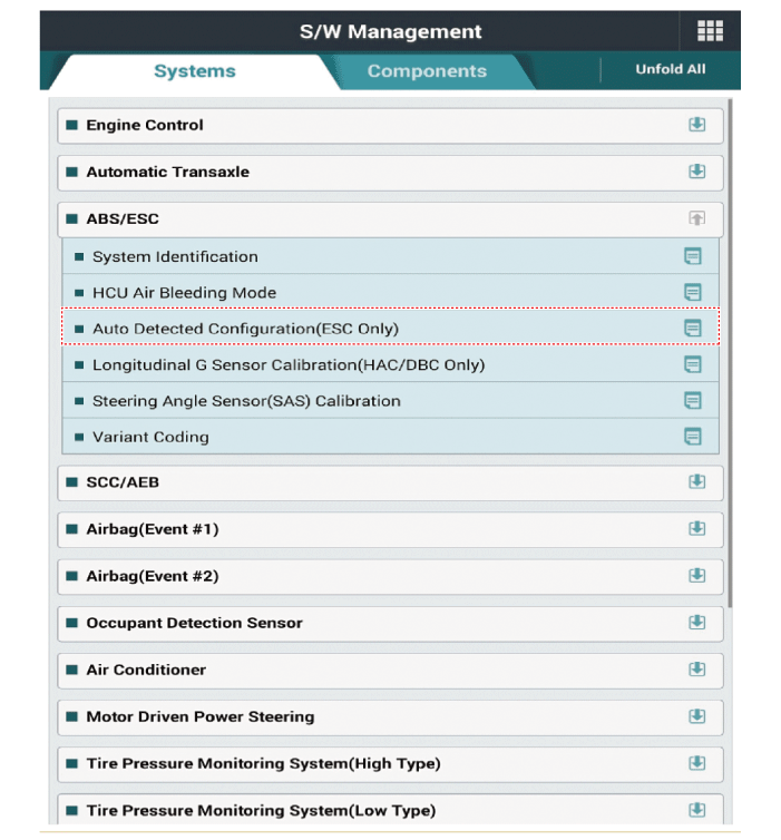
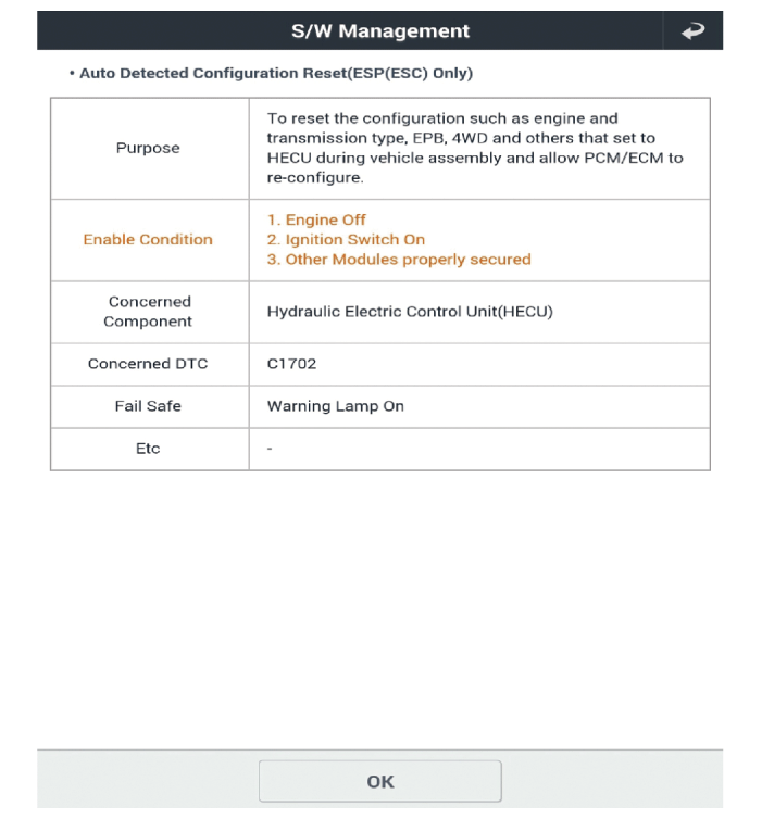
Conduct the Auto Detected Sensor Calibration. |
| 5. |
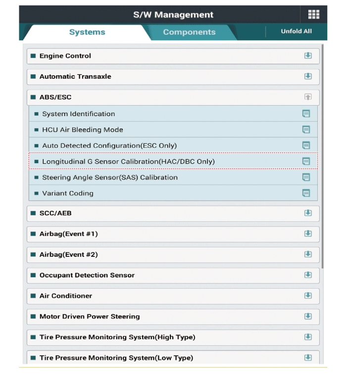
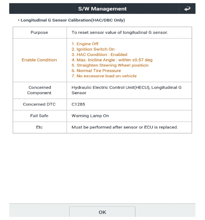
Conduct the Longitudinal G Sensor Calibration. |
| Diagnostic procedure by using diagnostic device |
Perform diagnostic procedure by using diagnostic device as shown below:
Connect self-diagnosis connector (16pins) located under the driver side crash pad to self-diagnosis device, and then turn the self-diagnosis device after key is ON.
Select the "vehicle model" and "ABS/ESC" on KDS vehicle selection screen, then select OK.
[Variant Coding]
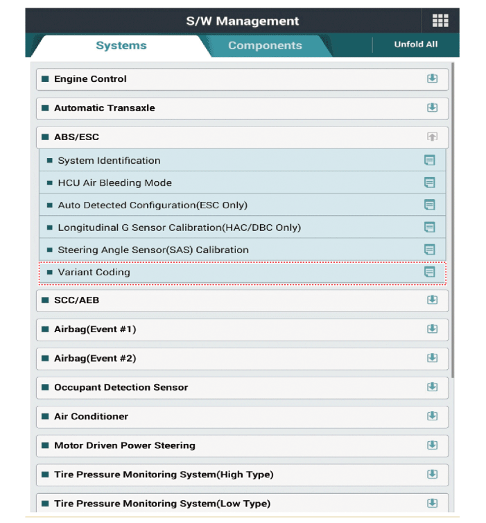
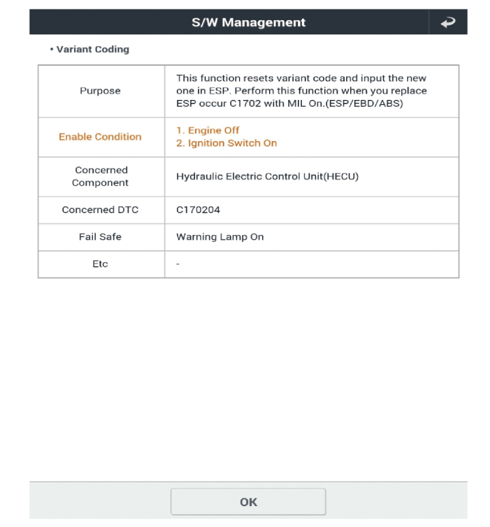
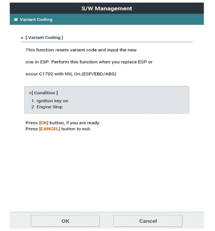
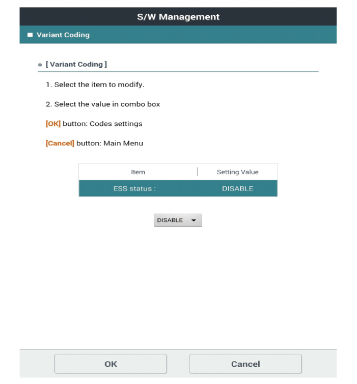
[Auto Detected Sensor Calibration]
[Longitudinal G Sensor Calibration]
 ESC (Electronic Stability Control) System
Components and components location
Components
1. ESC control module
2. Front wheel speed sensor
3. Rear wheel speed sensor
4. ABS Warning lamp
5. EBD / P ...
 Front Wheel Speed Sensor
Components and components location
Components
1. Front wheel speed sensor
2. Front wheel speed sensor connector
Repair procedures
Removal ...
Other information:
Kia Forte 2019-2025 (BD) Owners Manual: Instrument panel overview
1. Instrument cluster 2. Horn 3. Driver’s front air bag 4. Light control/Turn signals 5. Wiper/Washer 6. Ignition switch or ENGINE START/STOP button 7. Cruise control system Smart cruise control system 8. Drive mode button 9. Hazard warning flasher switch 10. Power outlet ...
Kia Forte 2019-2025 (BD) Service Manual: Ignition System
Description and operation Description Ignition timing is controlled by the electronic control ignition timing system. The standard reference ignition timing data for the engine operating conditions are pre-pro grammed in the memory of the ECM (Engine Control Module). The engine ...


