Kia Forte: Dual Clutch Transmission Control System / Gear Actuator Assembly
Components and components location
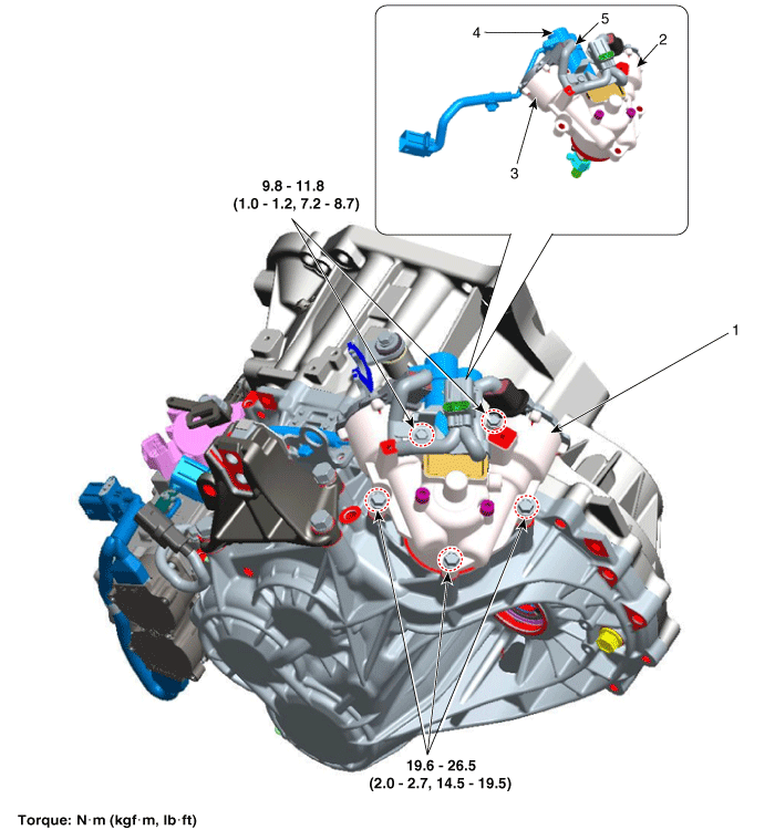
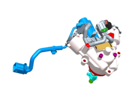
1. Gear actuator assembly
2. Shift motor (Even)
3. Shift motor (Odd)
|
4. Select solenoid (Even)
5. Select solenoid (Odd)
|
Specifications
Item
|
Specification
|
Resistance (line to line)
|
Shift motor 1/2
|
135.4 mΩ ± 10 %
|
Select solenoid 1/2
|
0.7 mΩ ± 10 %
|
Max. current
|
Shift motor 1/2
|
45 A
|
Select solenoid 1/2
|
20 A
|
Select solenoid sensor output
|
Push
|
4.0 ± 0.15 V
|
Pull
|
1.0 ± 0.15 V
|
Operating condition
|
-40 to 257°F (-40 to 125°C)
|
Rated voltage
|
13 V
|
Sensor supply voltage
|
8.75 V ± 10 %
|
Description and operation
| • |
The gear actuator comprises the shift motor and select solenoid.
|
| • |
Gear actuator shift motor and select solenoid use signals from TCM to
control the gear.
|
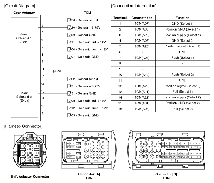
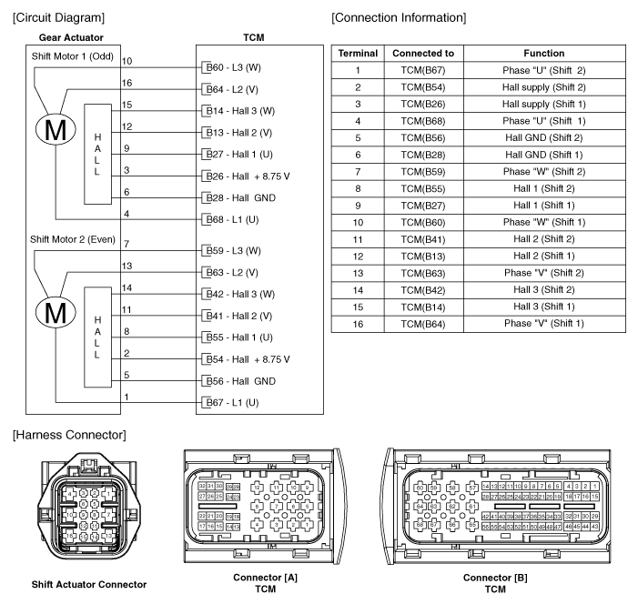
Schematic diagrams
Repair procedures
| 1. |
Move the shift lever to "N" range.
|
| 2. |
Remove the air cleaner assembly and air duct.
(Refer to Engine Mechnical System - "Air Cleaner")
|
| 3. |
Remove the battery and battery tray.
(Refer to Engine Electrical System - "Battery")
|
| 4. |
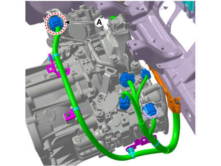
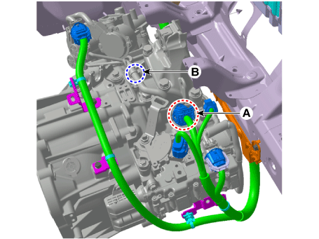
Disconnect the gear actuator motor connector (A).
|
| 5. |
Remove the wiring mounting clip (B) after disconnecting the gear actuator
solenoid connector (A).
|
| 6. |
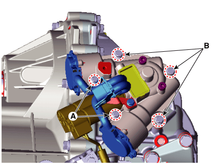
Remove the gear actuator assembly after loosening bolts (A, B).
|
Tightening torque :
(A) 9.8 - 11.8 N·m (1.0 - 1.2 kgf·m, 7.2 - 8.7 lb·ft)
(B) 19.6 - 26.5 N·m (2.0 - 2.7 kgf·m, 14.5 - 19.5 lb·ft)
|
|
| 1. |
Install in the reverse order of removal.
|
| • |
Check the following before installing the gear actuator assembly.
|
| 1) |
Check that the gear actuator is placed in the "neutral" state.
|
| 2) |
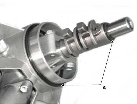
Check the assembled state of the O-rings (A).
|
| 3) |
Apply gear oil to the surface of O-rings.
|
| 4) |
Check the assembled state of the dowel pins (A).
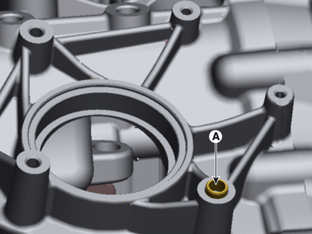
|
| • |
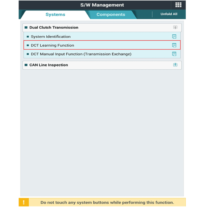
Perform the clutch touch point learning procedure using the KDS
after replacing the gear actuator assembly.
|
|
Components and components location
Component Location
1. Clutch actuator assembly
2. Fork cover
Specifications
Specification
...
Components and components location
Component Location
1. Input shaft speed sensor 1
(Odd)
2. Input shaft speed sensor 2
(Even)
Specification ...
Other information:
To fasten your seat belt:
To fasten your seat belt, pull it out of
the retractor and insert the metal tab
(1) into the buckle (2). There will be
an audible "click" when the tab locks
into the buckle.
The seat belt automatically adjusts to
the proper length only after the lap
belt por ...
Components and components location
Component Location
1. Cowl cross bar assembly
Repair procedures
Replacement
Put on gloves to prevent hand injuries.
...

 Clutch Actuator Assembly
 Input Speed Sensor 1